Please share the table you made, and thanks.
I haven't completed the amp yet so please validate if you're planning on using it as a reference...
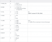
The numbers (1., 2., etc) refer to the O1, O2, O3 numbers on the PCB.
Oh, and a pretty cool feature in Adobe Acrobat is the measurement tool... attached is an example of what you can do:
Attachments
Last edited:
I like that idea, Tom. Sure a lot easier than layout.When I put together my DG300B, I found a good way to drill a pattern of many holes: Perf plate! I used a piece of perforated aluminum sheet as a drill guide. I marked two holes in the pattern, drilled those, and held the perf plate in place with a pair of brass pins. Drill rod would work too. Naturally, this requires the holes in the perf plate to be the same (or smaller, I suppose) diameter as the desired ventilation holes in the chassis.
Tom
Great minds think alike. I used this method to match-drill the holes for the bias adjustment pots and mounting screws (I'm building mine with a sub-plate). Once those holes were drilled on the sub-plate, I used it as a pattern to transfer them to the the main top plate using a drill press.When I put together my DG300B, I found a good way to drill a pattern of many holes: Perf plate! I used a piece of perforated aluminum sheet as a drill guide. I marked two holes in the pattern, drilled those, and held the perf plate in place with a pair of brass pins.
True. The pdf pattern is extremely accurate provided it's printed at the correct scale. However, I still found it necessary to do quite a bit of layout by measuring stuff directly from the finished board. For instance, the bias and CCS pots I used have their adjustment slots in a slightly different location than those shown on the pdf. For these measurements I used the depth gauge on a pair of cheap digital calipers.Sure a lot easier than layout.
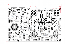
You'll also have to do layout work if you want to drill holes in a specific pattern. In my case I wanted to drill a complex pattern of ventilation holes around each power tube, (like you'd see in cross-drilled brake rotors, but with four different hole sizes). I created a CAD template, which simplified this process considerably by allowing me accurately place my prick punch on the exact center of each hole.
I like that idea, Tom. Sure a lot easier than layout.
It also made it possible to get all the holes aligned nicely. I forget how many holes I drilled in each top plate, but it was into the hundreds. It's nearly impossible to mark and drill a hole pattern by hand so that all the holes line up. And due to the pattern recognition feature in our brains, it doesn't take much misalignment for a hole to appear grossly off centre. The perf plate made all that a breeze.
Tom
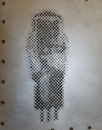
And how! Yesterday morning I had this crazy idea to do something completely different with the ventilation holes on my TSEII bottom plate. So I half-toned a picture of a 2A3 tube, printed several copies and got to work. Eight hours later I was rewarded with the results seen in the picture below.And due to the pattern recognition feature in our brains, it doesn't take much misalignment for a hole to appear grossly off centre.
This was done entirely by hand with relatively simple tools: Prick punch, center punch, drill press, about 20 different drill sizes, and an Opti-Visor.
I'm not sure I'll do this again.

Attachments
That's a whole lotta drilling!! I can see why you wouldn't want to do it again. I think I'd just use perf plate and fill the unwanted with puttyAnd how! Yesterday morning I had this crazy idea to do something completely different with the ventilation holes on my TSEII bottom plate. So I half-toned a picture of a 2A3 tube, printed several copies and got to work. Eight hours later I was rewarded with the results seen in the picture below.
This was done entirely by hand with relatively simple tools: Prick punch, center punch, drill press, about 20 different drill sizes, and an Opti-Visor.
I'm not sure I'll do this again.
")
And how! Yesterday morning I had this crazy idea to do something completely different with the ventilation holes on my TSEII bottom plate. So I half-toned a picture of a 2A3 tube, printed several copies and got to work. Eight hours later I was rewarded with the results seen in the picture below.
This was done entirely by hand with relatively simple tools: Prick punch, center punch, drill press, about 20 different drill sizes, and an Opti-Visor.
I'm not sure I'll do this again.
You should figure out how to incorporate that into your top panel, that is super cool!
Fantastic! Brilliant idea and very well executed!Yesterday morning I had this crazy idea to do something completely different with the ventilation holes on my TSEII bottom plate
You should figure out how to incorporate that into your top panel, that is super cool!
+1.
You should figure out how to incorporate that into your top panel, that is super cool!
I second that.
Thanks, everybody! I thought seriously about putting it on the top plate, but the area there is somewhat limited. I'd have had to use some seriously tiny drills, with the increased risks of bit breakage and hole misplacement. I like to think of it as an "Easter egg", one of those surprises that isn't apparent until one looks a little closer.
That said, I drew a lot of inspiration from evansc's website when doing the woodwork. The overall effect looks so simple at first glance, but it's deceptively so. There was a lot of planning and execution in the joinery and overall composition.
That's what I love about this hobby - there's a lot of creativity out there from a lot different people.
Yes, the parts list contains the wrong number for R4. The number you suggest will not work either since it should be a 5 watt part. This one is good:
150W-5-ND
I do not have the ability to change the BOM at this moment since I am currently traveling. I will fix it ASAP.
UPDATE 7-3-19 ------- BOM fixed
150W-5-ND
I do not have the ability to change the BOM at this moment since I am currently traveling. I will fix it ASAP.
UPDATE 7-3-19 ------- BOM fixed
Last edited:

Thanks, Jim! Hoping to bring this one to BA in November. I've waited a long time (far too long actually) to build a Tubelab SE, so I thought I'd do something special to celebrate.
Parenthetically, I discovered during the course of the build that I'd painted myself into a corner. I'd put the trimpots on top of the board for easy bias and CCS adjustment, but access to the actual measurement locations was still through the bottom of the amp - making any adjustments extremely awkward at best. Worse still, there wasn't any space left atop the chassis for test jacks.
I got a bolt of inspiration after staring at pictures of kilokat7's amp and found I still had usable space on the side. After several hours of drilling, filing, routing and swearing, the problem was solved. Now when the jacks arrive they'll be installed in a recessed bay where they'll be easily accessed, but shielded from dust, small animals and accidental poking from the occasional misplaced finger. I was even able to fabricate a nice little cover for them, too. I'll post some pictures when I get a chance.
Parenthetically, I discovered during the course of the build that I'd painted myself into a corner. I'd put the trimpots on top of the board for easy bias and CCS adjustment, but access to the actual measurement locations was still through the bottom of the amp - making any adjustments extremely awkward at best. Worse still, there wasn't any space left atop the chassis for test jacks.
I got a bolt of inspiration after staring at pictures of kilokat7's amp and found I still had usable space on the side. After several hours of drilling, filing, routing and swearing, the problem was solved.
Now when the jacks arrive they'll be installed in a recessed bay where they'll be easily accessed, but shielded from dust, small animals and accidental poking from the occasional misplaced finger. I was even able to fabricate a nice little cover for them, too. I'll post some pictures when I get a chance.
Last edited:
I completed checkout today and things are looking good overall. Connected the HD650 to the 32ohm tap and music was playing nicely.. plenty of volume too.
However, after the entire process was completed, B+ was measuring at 330V.
I think I prefer to bring it down to around 300V as a precaution.
I'm using:
Hammond 370EX PT
Hammond 159P 10H 144ohm choke
C4 is 4.7uF
I have an additional 60uF motor RUN cap for C5 which I have not connected yet.
PSUD shows that if I reduce 4.7uF to 3.3uF it will drop by another 15V..
Is that a reasonable approach or is 3.3uF too low?
Any other suggestions?
- Home
- More Vendors...
- Tubelab
- After a 14 year run, the TSE must DIE!