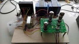
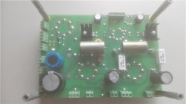
After ordering my board in january this year, it was time to get started on this amp. Ordered most parts from Mouser, unfortunately the RHRP15120 were not available so I left these out and used a GZ34 instead.
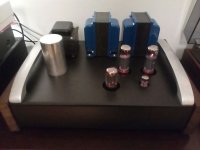
I was a little worried that I would have to use my only NOS Mullard GZ34, but after measuring some voltages, everything seemed to be ok and the amp works great, amazing sound, even on my small speakers, never knew these speakers could sound so good. Still have to build an enclosure for it, and after that I will try the amp on my big Wharfedale Kingsdale 3 speakers.
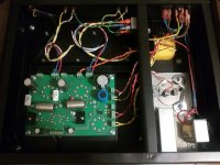
I used Edcor cxse25-8-5k output transformers and a vintage Robot Amsterdam power transformer. Because it only has a 220V primary, I had to put a dropping resistor in the 6.3V heater winding, the 5V heater winding is exactly 5V, even with the 234V mains I have here.
I ended up with a B+ voltage of 424V and there is 31.5V across the 560 ohm cathode resistor. This probably isn't the correct value, but the amp sounds good like this.
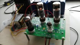
I didn't put in any switches and don't really see the need, it sounds great in the basic triode connection without feedback. Also don't need more power, the 5W the amp is making is way more than I need.
The coupling capacitors I didn't order from Mouser, really couldn't decide on anything they had to offer. I found a pair of vintage PIO Wima Durolit 0.22 uf / 630V. They measured 0.26 uf, which seems to be normal for these caps and after testing them for leakage up to 500V and checking the ESR, I decided to try them and am happy I did.
I am very happy with this amp and would like to thank George for making this great amp available.
Rob Debije.
I was a little worried that I would have to use my only NOS Mullard GZ34, but after measuring some voltages, everything seemed to be ok and the amp works great, amazing sound, even on my small speakers, never knew these speakers could sound so good. Still have to build an enclosure for it, and after that I will try the amp on my big Wharfedale Kingsdale 3 speakers.
I used Edcor cxse25-8-5k output transformers and a vintage Robot Amsterdam power transformer. Because it only has a 220V primary, I had to put a dropping resistor in the 6.3V heater winding, the 5V heater winding is exactly 5V, even with the 234V mains I have here.
I ended up with a B+ voltage of 424V and there is 31.5V across the 560 ohm cathode resistor. This probably isn't the correct value, but the amp sounds good like this.
I didn't put in any switches and don't really see the need, it sounds great in the basic triode connection without feedback. Also don't need more power, the 5W the amp is making is way more than I need.
The coupling capacitors I didn't order from Mouser, really couldn't decide on anything they had to offer. I found a pair of vintage PIO Wima Durolit 0.22 uf / 630V. They measured 0.26 uf, which seems to be normal for these caps and after testing them for leakage up to 500V and checking the ESR, I decided to try them and am happy I did.
I am very happy with this amp and would like to thank George for making this great amp available.
Rob Debije.
Attachments
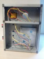
When the enclosure is finished, I will post pictures. It may take a while, because I would like to make a modular enclosure out of steel. The chassis will be 3 pieces, one with the power transformer on top, one with both output transformers on top and in front of these 2 a box with the pcb and under it the choke. I will also make a cover for all 3 transformers, so when everything is together you will not see the seperate pieces. I think this layout will allow me to change transformers easily without rebuilding the complete amp.
Rob Debije.
Rob Debije.
I think the Edcor opt's are great. I was lucky, bought them from a guy in Germany who ordered 4 and wasn't going to use the other 2.
I just started with this hobby, so I may build some more amps. I think by making this amp modular I can change any part of the amp, just build a new sub chassis for the part I would like to change. It may keep this hobby a bit more affordable. Will be testing another power transformer later this week, should give some more B+, The 424V I get now seems a bit low.
I just started with this hobby, so I may build some more amps. I think by making this amp modular I can change any part of the amp, just build a new sub chassis for the part I would like to change. It may keep this hobby a bit more affordable. Will be testing another power transformer later this week, should give some more B+, The 424V I get now seems a bit low.
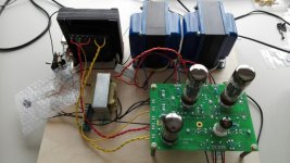
I just replaced the Robot power transformer with one out of an Elk Custom 60 guitar amp. B+ has gone up from 424V to 458V. The Robot transformer was very noisy, this one is almost silent.
I did find a second pair of the big Wharfedale Kingsdale speakers, so I have them connected now. These are 6 ohm, and my Edcor opt's are 8 ohm. With the other power transformer they actually sounded worse than the small 8 okm speakers I first had connected, now with the Elk transformer they sound great.
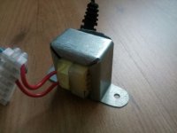
The is a connection marked E on the Elk power transformer, not sure yet if this is a shield that should be connected to ground. I didn't connect it because there seems to be an AC voltage of 130V between E and ground. If it is a shield, this voltage probably shouldn't be there? Also this transformer seems to be running hotter than the other one. It is up to 50 degrees C after a few hours while the robot transformer would not get warmer than 44 degrees C.
I did find a second pair of the big Wharfedale Kingsdale speakers, so I have them connected now. These are 6 ohm, and my Edcor opt's are 8 ohm. With the other power transformer they actually sounded worse than the small 8 okm speakers I first had connected, now with the Elk transformer they sound great.
The is a connection marked E on the Elk power transformer, not sure yet if this is a shield that should be connected to ground. I didn't connect it because there seems to be an AC voltage of 130V between E and ground. If it is a shield, this voltage probably shouldn't be there? Also this transformer seems to be running hotter than the other one. It is up to 50 degrees C after a few hours while the robot transformer would not get warmer than 44 degrees C.


Well it seems I have a new problem. During the day the line voltage was about 228V which resulted in a B+ of 458V and a heater voltage after the .05 ohm resistor of 6.3V.
When I tried the amp again after midnight, the line voltage had gone up to 232.5V which resulted in a B+ of 473V and a heater voltage of 6.46V after the resistor.
I did experiment with a few small transformers as a bucking transformer, but couldn't get the voltage high enough for the primary which should have 220V. Also at 228V the 5V tap resulted in exactly 5V at the GZ34 heater.
Not sure what would be the best solution for this, I could buy a new Hammond power transformer, but since this has 220V or 240V primary and not 230V I may get the same problems I have now.
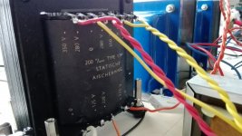
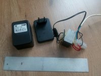
Today I tried a large toriod transformer I had and wired it as a bucking transformer. It lowered the ac mains about 9V. The primairy voltage on the power transformer remained between 220V and 222V all evening and after midnight it went up to 224V. I am happy with this result.
The power transformer runs a bit cooler now, B+ is slightly lower at 441V, heater voltages are ok and I don't need the 0.05 ohm dropping resistor anymore in the 6.3V heater tap. HT voltage is 770V AC now, which is also better, it was about 828V when B+ got up to 473V.
Time to start work on the case and either find a smaller bucking transformer that can be built inside the case, or use the big 220VA toroid in a seperate case for now.
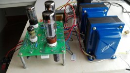
It has been a while, but finally the amp is finished. I found a small 6V 2 amp transformer that I built in as a bucking transformer. The amp plays very good and there is no humm. I built the chassis out of 1.2 mm steel. There is a sub chassis for the choke, bucking transformer and motor run cap. The pcb is mounted to an aluminium plate under the chassis. It has been a fun project, now it's time to listen to the amp.
Rob.
Rob.
Attachments
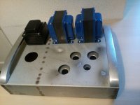
Thanks, this was my first attempt at making a case for an amplifier. I did copy some ideas for the case from rknize, I am lucky to own a spotwelder, so that is why I chose steel for the case. I also was lucky to find a greenlee hole punch set.
I had to make a mount for the small bucking transformer, this was a wall wrat that was impossible to mount. If I had to do it again I probably would have bought a new power transformer, this used one operates at 220V and today we have about 230V over here. This raises all secondary voltages. With the bucking transformer, the voltages are better. The power transformer does vibrate a little, even after mounting it on rubber. So unfortunately used parts are not always a good idea in building amps, I guess.
The case however has been made completely out of surplus materials, either found at the local scrapyard or just found for free. The wood is some kind of hard wood I found that looked really ugly. after taking a few mm off, it looked very nice, so I used it for the sides.
Rob.
Attachments
- Status
- This old topic is closed. If you want to reopen this topic, contact a moderator using the "Report Post" button.
- Home
- More Vendors...
- Tubelab
- Another working Tubelab SSE