My SSE has been built and has undergone initial checkout, I am now letting it play for a few hours using cheap Chinese el34's.
I will probably roll some other tubes in after Im more secure in my work. lol
But I have to say George your amp sounds ssooooo ggoooodd!! Thank you for taking the time designing it so even us noobs can enjoy building a great sounding amp the first time.
Hell they even made these Bose 201's sound decent, I used them because I only paid $1.00 each for them at a garage sale!! haha
I will attach my ADC 404's later and see how they sound.
Thanks to everyone that gave me advice and help.
") Need pictures or it didn't happen..
Need pictures or it didn't happen..Riven67, in tube rolling, I found in my SSE the 12at7 tube made a huge difference in the sound.
I started with a Jan/Phillips then Mullard, Telefunken, and RCA black plate. All nos.
Power tubes I’ve tried el34s, kt77s, and kt88s.
Fun.
( Led Zepplin on kt88s, with Telefunken was too much base. ?)
I started with a Jan/Phillips then Mullard, Telefunken, and RCA black plate. All nos.
Power tubes I’ve tried el34s, kt77s, and kt88s.
Fun.
( Led Zepplin on kt88s, with Telefunken was too much base. ?)
Riven67, in tube rolling, I found in my SSE the 12at7 tube made a huge difference in the sound.
I started with a Jan/Phillips then Mullard, Telefunken, and RCA black plate. All nos.
Power tubes I’ve tried el34s, kt77s, and kt88s.
Fun.
( Led Zepplin on kt88s, with Telefunken was too much base. ?)
I've got a boatload of 12at7's all makes and a few equivalents as well,
I'll try em as soon as I get the chance to dig them out as they are still in boxes from the move.
Help needed with some final details for my build!
Ok so all the tests worked fine no magic smoke came out of the amp during testing, so I'm very happy with the way it works and sounds.
So onto the final design of the finished amp.......this is where I need some help with some of the things I'd like to do.
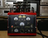
I love the "Man Cave" version of the SSE from this thread Man Cave
I'd like to add some of his ideas into my final design, though my chassis will look nothing like his.
Some of the things he's added intrigue me but I'm not sure how to duplicate them. So here's my issues I need help with.
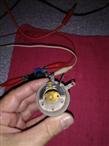
1. VU meters - i bought these VU Meter set w/driver pcb
But even after reading a bunch of threads with little or no answers I still don't know what source to hook up to the pcb. On the pcb is a 3 part connection one for left in, right in, and ground, is this for a connection from the positive side of the line in jacks? Ground would go to the star or can I use the unused connector on the sse board? I know this is a real beginners question but honestly no one answered this in any of the threads I read and I just don't know.
2. Cathode bias meters and adjustments. On the Man cave thread he states he used some old heliopots in place of R17 & R27. And what does he mean "shunts for the meters" That seems easy enough to do but I don't have heliopots would a good wire wound potentiometer work? And if so what's the specs and a good value to use in this spot? And how is it wired? One side To each of the resister holes on the board with the wiper connected to one of the other pins? And how do I install "shunts" for the meters? (SEE I really do need help lol)
3. I'm also interested in the B+ adjustment and meter. Although I have no idea how this was made to work. Anyone have any ideas how it was implemented ? I tried asking on the thread but the member has not answered in over a year so i thought I'd throw it out there and see if perhaps someone with more experience would answer. Any schematics or how to would be greatly appreciated. I don't think adding a wire wound pot to the circuit here would be a good idea but really have no idea how this was done.
If anyone knows the original builder of the Man Cave SSE and can get in touch with him to ask how it was done I would absolutely be thankful.
Anyway I am looking forward to putting my amp into a chassis and putting it in a place of honor in the living room. I have an aluminum topplate and have some really nice colorful wood dyes, now I am looking into getting some exotic woods for the skirt. I'll post some pics as I go. Thanks in ADVANCE!
Attached pic of VU meters and pic from Man Cave amp for those who don't want to follow the link. I take no credit for that amp it is totally someone else's creation that I admire.
Ok so all the tests worked fine no magic smoke came out of the amp during testing, so I'm very happy with the way it works and sounds.
So onto the final design of the finished amp.......this is where I need some help with some of the things I'd like to do.
I love the "Man Cave" version of the SSE from this thread Man Cave
I'd like to add some of his ideas into my final design, though my chassis will look nothing like his.
Some of the things he's added intrigue me but I'm not sure how to duplicate them. So here's my issues I need help with.
1. VU meters - i bought these VU Meter set w/driver pcb
But even after reading a bunch of threads with little or no answers I still don't know what source to hook up to the pcb. On the pcb is a 3 part connection one for left in, right in, and ground, is this for a connection from the positive side of the line in jacks? Ground would go to the star or can I use the unused connector on the sse board? I know this is a real beginners question but honestly no one answered this in any of the threads I read and I just don't know.
2. Cathode bias meters and adjustments. On the Man cave thread he states he used some old heliopots in place of R17 & R27. And what does he mean "shunts for the meters" That seems easy enough to do but I don't have heliopots would a good wire wound potentiometer work? And if so what's the specs and a good value to use in this spot? And how is it wired? One side To each of the resister holes on the board with the wiper connected to one of the other pins? And how do I install "shunts" for the meters? (SEE I really do need help lol)
3. I'm also interested in the B+ adjustment and meter. Although I have no idea how this was made to work. Anyone have any ideas how it was implemented ? I tried asking on the thread but the member has not answered in over a year so i thought I'd throw it out there and see if perhaps someone with more experience would answer. Any schematics or how to would be greatly appreciated. I don't think adding a wire wound pot to the circuit here would be a good idea but really have no idea how this was done.
If anyone knows the original builder of the Man Cave SSE and can get in touch with him to ask how it was done I would absolutely be thankful.
Anyway I am looking forward to putting my amp into a chassis and putting it in a place of honor in the living room. I have an aluminum topplate and have some really nice colorful wood dyes, now I am looking into getting some exotic woods for the skirt. I'll post some pics as I go. Thanks in ADVANCE!
Attached pic of VU meters and pic from Man Cave amp for those who don't want to follow the link. I take no credit for that amp it is totally someone else's creation that I admire.
Attachments
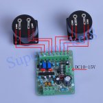
The eBay ad said the sensitivity was -15 dB, which doesn't really tell much. I suppose you would attach those board inputs to the speaker output of the amp, and use the 10 turn potentiometer to set the meter to read 0 dB at the amplifier clipping point, or some other arbitrary point, such as 1 watt. Were there no instructions?
If you want to use a variable resistor for the bias resistor s, 1K would be about right I would think. Clarostat use to make these, I have some 25 watt ones I picked up at hamfests and use on the bench. I wouldn't use less than 25 watt parts, probably. It looks like that fellow has some old style 10 turn counters with a lock to run the bias pots. These are not real common these days. Philmore used to import a cheap plastic line with a vernier. Real ones are sometimes found at hamfests. Fair Radio or Surplus Sales of Nebraska probably also have them. These are $1 or $2 parts at hamfests, but will not likely be inexpensive from a surplus house.
I didn't see anything on that amp to adjust the B+ - it just looked like there was a chinesium meter on the AC line and on the B+ line for eye candy. Different rectifier tubes have different voltage drops and can be used to somewhat adjust the loaded B+ voltage. You do not want to use a potentiometer ( ohms law ).
Hope this helps. Others may have different thoughts.
Win W5JAG
No instructions were included, I had to search for that photo in other auctions for the same set of meters.The eBay ad said the sensitivity was -15 dB, which doesn't really tell much. I suppose you would attach those board inputs to the speaker output of the amp, and use the 10 turn potentiometer to set the meter to read 0 dB at the amplifier clipping point, or some other arbitrary point, such as 1 watt. Were there no instructions?
If you want to use a variable resistor for the bias resistor s, 1K would be about right I would think. Clarostat use to make these, I have some 25 watt ones I picked up at hamfests and use on the bench. I wouldn't use less than 25 watt parts, probably. It looks like that fellow has some old style 10 turn counters with a lock to run the bias pots. These are not real common these days. Philmore used to import a cheap plastic line with a vernier. Real ones are sometimes found at hamfests. Fair Radio or Surplus Sales of Nebraska probably also have them. These are $1 or $2 parts at hamfests, but will not likely be inexpensive from a surplus house.
Thanks, Yes the original "Heliopot" is not that common these days, and they are not cheap when you do find them. But knowing what specs to look for i'm sure i can find a suitable pot.
I didn't see anything on that amp to adjust the B+ - it just looked like there was a chinesium meter on the AC line and on the B+ line for eye candy. Different rectifier tubes have different voltage drops and can be used to somewhat adjust the loaded B+ voltage. You do not want to use a potentiometer ( ohms law ).
Oh my mistake, I thought the dial under the B+ Meter was for that although I didn't understand why he'd call it an attenuator. Doh!! Thats the volume control!! Lol ok so I'm an idiot, in this case.
Yes it did indeed, thank you!Hope this helps. Others may have different thoughts.
Win W5JAG[/QUOTE]
Not to nit pick, but they are "helipot".
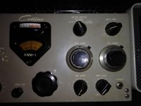
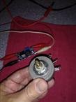
I've attached a better pic of what the turns counter look like, and a pic of the ceramic Clarostat that I use. This is a 25 watt, 1K, single turn part.
SSON has multiturn helipot style parts, but I only saw five and ten watt parts in 1 and 2K values. That may be adequate for a ceramic wirewound device, but I'm not sure how robust those multi turn parts are. DC current through a regular carbon type pot will eventually make it noisy, and I'm not sure how good those multi turn pots are at dissipating heat. So to my mind, bigger equals better at holding off these potential problems.
Personally, I would use a single turn wirewound ceramic with a big knob if you want easier resolution. It's not like high precision is needed .....
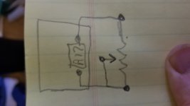
The better way to wire one is to short the wiper to one end of the pot, so that it is simply shorting out a part of the resistance. This way if the wiper opens, the full value of the pot is in circuit, rather than creating an open circuit.
Anyone who reads my posts and threads know that I make a lot of mistakes. Whatever I know is from practical experience, some of it learned the hard way, from simply stupid, to spectacular. If George sees this, he is the expert on these matters. Others may also have thoughts on the matter.
Win W5JAG
I've attached a better pic of what the turns counter look like, and a pic of the ceramic Clarostat that I use. This is a 25 watt, 1K, single turn part.
SSON has multiturn helipot style parts, but I only saw five and ten watt parts in 1 and 2K values. That may be adequate for a ceramic wirewound device, but I'm not sure how robust those multi turn parts are. DC current through a regular carbon type pot will eventually make it noisy, and I'm not sure how good those multi turn pots are at dissipating heat. So to my mind, bigger equals better at holding off these potential problems.
Personally, I would use a single turn wirewound ceramic with a big knob if you want easier resolution. It's not like high precision is needed .....
The better way to wire one is to short the wiper to one end of the pot, so that it is simply shorting out a part of the resistance. This way if the wiper opens, the full value of the pot is in circuit, rather than creating an open circuit.
Anyone who reads my posts and threads know that I make a lot of mistakes. Whatever I know is from practical experience, some of it learned the hard way, from simply stupid, to spectacular. If George sees this, he is the expert on these matters. Others may also have thoughts on the matter.
Win W5JAG
Attachments
Yes i realized i was spelling it wrong while searching the auction site for them! HahaNot to nit pick, but they are "helipot".
Yes i agree, i may even have some like the ones you posted photos of. ThanksI've attached a better pic of what the turns counter look like, and a pic of the ceramic Clarostat that I use. This is a 25 watt, 1K, single turn part.
SSON has multiturn helipot style parts, but I only saw five and ten watt parts in 1 and 2K values. That may be adequate for a ceramic wirewound device, but I'm not sure how robust those multi turn parts are. DC current through a regular carbon type pot will eventually make it noisy, and I'm not sure how good those multi turn pots are at dissipating heat. So to my mind, bigger equals better at holding off these potential problems.
Personally, I would use a single turn wirewound ceramic with a big knob if you want easier resolution. It's not like high precision is needed .....
The better way to wire one is to short the wiper to one end of the pot, so that it is simply shorting out a part of the resistance. This way if the wiper opens, the full value of the pot is in circuit, rather than creating an open circuit.
Ok, you mean like the attached hand drawn schematic example?
Anyone who reads my posts and threads know that I make a lot of mistakes. Whatever I know is from practical experience, some of it learned the hard way, from simply stupid, to spectacular. If George sees this, he is the expert on these matters. Others may also have thoughts on the matter.
Win W5JAG
Attachments
Well I'm collecting materials for my chassis and final build. Being on a tight budget right now, as I'm in the process of buying a home, I'm using what I have or can obtain cheap.
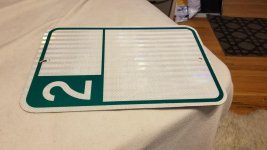
My brother gave me this aluminum street sign that is 12 x 15 so it's plenty big enough.
I removed the letters and numbers and am trying to decide if I want to keep the border or remove it also. I also have to decide if I want to use the reflective side or flip it and use the bare metal side for the top plate.
I need some wood to build a base for it but i can get that for next to nothing and finish it nicely.
One step at a time, I'll keep posting updates as I get closer to a finished amp.
Attachments
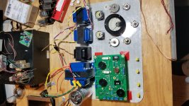
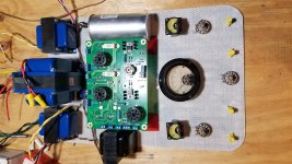
While I'm still deciding on the shape of the chassis, I was playing around with different layouts and boy is it going to be crowded.
Oh and I made a mistake the plate is actually 12 x 18 not 12 x 15 that I stated in my last post.
In the 2nd pic the choke and aux capacitor would actually be hidden underneath the plate not crammed in next to the tubes.
Any thoughts on placement of the transformers ? If anyone spots any obvious mistakes please let me know! Thanks
Attachments
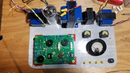
Just wondering, maybe pic 1's layout, but the choke, can cap, and PT switching places with the OPT... The yellow wire nuts laid out like pic 3 with the gauges... And then the knobs on the front face...
I probably ought to be the last one commenting on layout because mine are embarrassing at times (drill one hole and then ask, "what was I thinking?") and everything ends up getting moved around again.
I probably ought to be the last one commenting on layout because mine are embarrassing at times (drill one hole and then ask, "what was I thinking?") and everything ends up getting moved around again.
I like #2, with the suggestion of just making the depth of the wooden box deep enough to put the capacitor and choke underneath the aluminum plate.
Win W5JAG
You asked about meter shunts - here's something:
http://soaraperformance.com/wp-content/uploads/2017/01/Meter-shants-and-multipliers.pdf
can't post it directly since it has a copyright notice - I've seen several different entities claiming the copyright ....
Win W5JAG
You asked about meter shunts - here's something:
http://soaraperformance.com/wp-content/uploads/2017/01/Meter-shants-and-multipliers.pdf
can't post it directly since it has a copyright notice - I've seen several different entities claiming the copyright ....
Last edited:
Just wondering, maybe pic 1's layout, but the choke, can cap, and PT switching places with the OPT... The yellow wire nuts laid out like pic 3 with the gauges... And then the knobs on the front face...
I probably ought to be the last one commenting on layout because mine are embarrassing at times (drill one hole and then ask, "what was I thinking?") and everything ends up getting moved around again.
Lol I guess I should have mentioned........
The wire nuts are standings for the switches, on/off, ss/rectifier, ul/tri, cfb/no cfb.
The large pots are standings for ma meters. The smaller pots are just what they are pot for volume and adjustable bias.
Last edited:
- Status
- This old topic is closed. If you want to reopen this topic, contact a moderator using the "Report Post" button.
- Home
- More Vendors...
- Tubelab
- Another SSE is Born!!