Yes, at the time the TSE was being I tested a bunch of caps for ESR and ESL since we had a fancy HP component analyzer at work that tested parts from DC to several hundred MHz (500?). The 5842 driver tube used in the TSE liked to oscillate in the 50 to 200 MHz region, so I selected the best parts I could get from DigiKey to get that cathode at a RF ground. The first two prototypes actually used two caps in parallel, an electrolytic and a Tantalum. I still have one of those boards, the other was destroyed.
I went through the same steps for the SSE, but the 12AT7 does not have the Gm that the 5842 has, so it's not nearly as prone to oscillation.
This was over 10 years ago and capacitor technology has improved a lot. I'm sure the criteria I used to pick that part years ago is no longer valid, but I don't have access to Motorola's lab, as I don't work there any more, and the lab no longer exists.
Feel free to use any cap you see fit in the SSE, but I would avoid ultra cheap no name stuff, because the 12AT7 IS an RF tube and it will oscillate if the conditions are right.
The TSE is a bit more critical and I have seen those things oscillate. You are pretty safe if there is a 4.7K or larger carbon COMP stopper resistor on the grid, but do use a decent low ESR and ESL cap on that cathode. The exact value is not critical, and some of the really big ones may have too much inductance and promote oscillation.
I usually elevate the heaters for both tubes to 50 - 70 volts for most cases. That puts the heater 50 to 70 volts more positive that the cathode of V1, which is within spec, and well below 200 volts more negative than the cathode of V2 (in spec) even with signal swing. This assumes a 6CG7 or 6FQ7 for V2. It's worth a check and possible voltage change if other tubes are used.
Thanks George. I'm using 6CG7s. I've separated the heaters for V1 and V2 in my breadboard on the bench but when I finally choose an output stage and build a couple of amps for real I'll do as you did.
I ordered 50 more boards identical to these. They should arrive in early January.
I would like to buy some. Will they go to your “Ordering page” on Tubelab | Dedicated to advancing the state of the art in affordable high end audio. I looked and did not see the UDB listed.
Sorry, I spent my day on the road and in airplanes and airports including the cluster called ohare. Left rural West Virginia early this morning, landed in San Diego this afternoon, then caught an Uber for a 40 mile ride.
The UD boards will make it to the web site when I get the time to update the site. Time for Tubelab stuff is very limited right now due to the contract engineering job. I will post here as soon as the boards arrive and they can be ordered as described in post#29.
Full parts lists, construction details and a couple amp builds will have to wait for some time to do them.
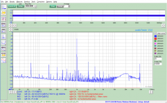
One watt out with -20dB GNFB. 6P1P input with 6CG7 driver.
My current sound card is the Xonar SE which boasts .002%thd, but in loopback shows more like 0.022%thd.
I have a 20dB attenuator on the input. I also have a 220ohm series resistor and a pair of back-to-back 2.4V Zener diodes to prevent overloading the input and blowing the sound card. Not that I have ever blown a sound card.
My current sound card is the Xonar SE which boasts .002%thd, but in loopback shows more like 0.022%thd.
I have a 20dB attenuator on the input. I also have a 220ohm series resistor and a pair of back-to-back 2.4V Zener diodes to prevent overloading the input and blowing the sound card.
Not that I have ever blown a sound card.Attachments
I'm working with GNFB right now. I plan on testing with 6N23P / 6DJ8 with the 6CG7 as well. I may try 12AT7/12FG7 combo also.
Once I finish with GNFB, I'll switch to plate to plate/grid feedback and see how it compares, then try a combination of both as nested feedback.
I plan on getting a better sound card, but until I'm satisfied I won't blow up the next one, I'll stick with the Xonar SE.
The Xonar SE starts distorting on the input above 1Vrms, both in loop-back and if I use my IG-18 as the input.
Anyone with suggestions for a protection network with a sharper knee than a zener, speak up. I suspect the zener diodes are contributing to distortion.
Last edited:
I need to dig out another 6N23P to see if I have a problem with the one I'm using.
When I was using it and powered up, it took 15-20 minutes to stabilize out, whereas the 6N1P hardly drifts at all.
I can get up to about -27dB GNFB before it breaks into oscillation. I'm using a 500pF silver Mica cap in parallel with the feedback resistor from the output of the OPT. I'm setting the feedback to -20dB for most tests to give me 7dB margin. I have a switch to select between GNFB and no GNFB.
With AudioTester it is easy to select the output level and add or subtract 20dB depending on whether or not the feedback is in place.
Last edited:
6N23P and 6DJ8 produce very similar graphs. Both show slightly higher noise compared to the 6N1P, and have slightly higher third harmonic distortion (without GNFB).
Once GNFB is introduced, the results is nearly identical on the FFTs.
It will be interesting to see if I can hear any difference.
Once GNFB is introduced, the results is nearly identical on the FFTs.
It will be interesting to see if I can hear any difference.
What output tubes are you driving?
I'm running 6P3S at 400V, 40mA bias, with a 5K OPT.
I'm getting about 20W out before I hit grid current. Once it starts drawing grid current, I see the distortion increase rapidly from less than 1% to about 8% at clipping (40W out).
I'm considering reducing the pull down resistors to increase the bias current in the FETS to see if that reduces the distortion any.
I will be surprised if it makes much difference.
It didn't.
I changed the bias resistors from 82K to30K and distortion dropped slightly near transition to AB2, but increased slightly higher output levels.
Last edited:
Had to go look at son in law's dead car. Tomorrow I get to go fix it.....the fun never stops.
I like to keep 10 to 20 mA flowing through the mosfets at idle since their Gm drops at low currents. I usually use the Triad N-68X to make +/- 150 to 160 volts, mainly because of it's low price. On real music grid current will flow rarely, just on music peaks.
Unless you are playing highly compressed dance music into clipping, most music has at least a 10dB peak to average ratio, often well above 20 dB. This means that a 100 WPC amp averages 1 to 10 watts when pushed to clipping on peaks. The power supply caps will provide the current pulses for the peaks, the transformer is heated by the average power consumption.
Bob Carver made his career undersizing power transformers and heat sinks in solid state audio amps. The manual clearly stated that the product was intended for home audio use only, and NOT to use it for sound reinforcement or MI use. I played my guitar through my M-400 a lot and ran 4 ohm speakers on it. Chasing the neighbor kids with their ghetto blasters away with a fully cranked guitar occasionally tripped the protection shutdown, but the amp was still working when I gave it away prior to leaving Florida. It survived 30+ years of my abuse.
We can do the same, to an extent with our tube amps. The power transformers and output tube plate dissipation ratings need to be capable of covering the idle current, plus some margin if the amp will be used for home HiFi. You need a bigger margin for a guitar amp. The size of this margin depends on how the amp will be used, how efficient the speakers and how conservative you want to be. Several of my amps would red plate if pushed to full power with a continuous sine wave for 20 minutes or so. Playing the same amp at ear splitting volume levels for hours didn't bother it at all. I have a modified version of pete Millett's Engineers Amp tuned up to 125 WPC. Several of these were built by others according to the same formula, all with 6HJ5 tubes. None ever blew up, and I had a habit of cranking mine up to the edge of clipping and leaving it there while I went outside to mow my lawn.....without hearing the lawnmower. That amp is still living, prompting Pete to make a conservative 50 watt mono version.
I use a 50 VA isolation transformer for my amps. I believe that a 25 VA transformer would be fine. I bought a Triad and a Hammond 12 VA transformer, but haven't tried them yet.
Realistically I am just playing with toys.
My speakers are 96dB/W, and I have measured peaks at 1W at what I consider party background music.
I rarely crank it up, so even a 20W amp should be more than sufficient for my use. I'm just playing with AB2 to see what I can get without overly complicating the design.
My speakers are 96dB/W, and I have measured peaks at 1W at what I consider party background music.
I rarely crank it up, so even a 20W amp should be more than sufficient for my use. I'm just playing with AB2 to see what I can get without overly complicating the design.
Realistically I am just playing with toys.
My speakers are 96dB/W, and I have measured peaks at 1W at what I consider party background music.
I rarely crank it up, so even a 20W amp should be more than sufficient for my use. I'm just playing with AB2 to see what I can get without overly complicating the design.
Same here.....my 95dB speakers are plenty loud with my TSE driving them.....but I've got a stash of really nice iron in the closet saying "use me"...
- Home
- More Vendors...
- Tubelab
- Tubelab Universal Driver Board, 2015 version