Yes, that looks good.
I use a 10 R resistor in the cathode to give easier reading of the cathode current as most of my meters are not real accurate in the low mv range. The 10R resistor does not give much feedback, but gives 10X the voltage for setting the cathode current.
Apples and oranges.
I use a 10 R resistor in the cathode to give easier reading of the cathode current as most of my meters are not real accurate in the low mv range. The 10R resistor does not give much feedback, but gives 10X the voltage for setting the cathode current.
Apples and oranges.
My boards can be ordered by sending payment via Paypal to the Tubelab email address (see below). Make sure that Paypal has your correct shipping address on file, or provide it in the comments box. State which board or boards you want, and how many in the comments box, or send a separate email with this information within a few minutes of sending payment, so that I can match it with the order.
The SSE, SPP, and TSE boards are $35 USD each. Each board makes a stereo amp with power supply.
The board described in this thread is called the UD or Universal Driver board. It is $25 due to its smaller size. Each board makes a single channel driver. Two boards are required for stereo, and a power supply for the amp is needed.
A suitable power supply schematic will be posted soon, and a PC board for it should be available within a month or two depending on PCB delivery times. I buy my current boards in batches of 100 with a 4 week delivery time to get an acceptable price. That may not be an option this time.
Shipping for 1 to 4 boards in the USA is $8. International shipment is $15.
I do not post my complete email address in plain text format in an attempt to control spam. Even still I get 20 to 30 useless emails a day. My personal email address that I have had for over 25 years gets over 100 spams a day, many loaded with evil payloads.
The address is "tech AT tubelab.com" remove the AT and replace it with the appropriate symbol without the spaces or quotes.
Will the Universal Power Supply board that is available at the DIYAudio Store work as the power supply for this amp? If I am way off base please excuse my ignorance. I'm a complete idiot when it comes to electronics.
George, you may have gotten the notice but in case you didn't:
"Mouser Electronics received a lifecycle change notification from the manufacturer regarding a product you had interest in or purchased within the last two years. Please click on the part number to view product details and similar products for replacements.
Manufacturer Part # Mouser Part # PO# Part Status
Bourns 3309P-1-102 652-3309P-1-102 13901034 End of Life
Bourns 3309P-1-104 652-3309P-1-104 13901034 End of Life
"

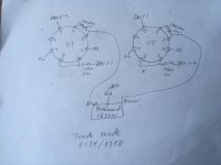
Simulation of Feedback options
I’ve been simulating various feedback options for the UDB with 6550 outputs.
The open loop schematic is shown below.

I’ve run simulations of the following feedback options:
· 470K output anode to driver anode (1dB),
· output anode to driver anode plus second LTP anode to first LTP anode 540K (lowest recommended), additional 1.5dB,
· output anode to driver anode plus second LTP anode to first LTP anode plus global (100R/2K7, additional 9.3dB)
· cathode ( 0.5H, 4dB) and
· cathode plus global (100R/2K7, additional 10dB).
The Universal Driver Board is easily capable of swinging the voltage required for cathode feedback.
Output power for these options into 8Ω is shown below:

and for less than 10W

Observations:
The lowest recommended resistor (470K) from the output anode to driver anode only provides 1dB of feedback. This provides some improvement in THD up to about 45W but provides no improvement over open loop above that.
540K between the LTP anodes only adds a further 1.5dB but no improvement in THD.
The addition of 9dB global negative feedback is worse than open loop below 6W but provides significant improvement above that.
Just adding 4dB of cathode feedback provides comparable performance to the output anode to driver anode plus LTP anode and global feedback below 40W and significantly better performance above that.
Adding 10dB of global feedback to the cathode feedback reduces THD to less than 0.1% below 10W and below 0.3% all the way to 60W.
Conclusion:
I'll try, measure and listen to all the options, but cathode feedback looks to be the way to go.
There are at least 2 vendors of the specialist toroidal transformers required. I’m planning on adding bias servos to ensure the output tube quiescent currents are as close as possible.
I’ve been simulating various feedback options for the UDB with 6550 outputs.
The open loop schematic is shown below.
I’ve run simulations of the following feedback options:
· 470K output anode to driver anode (1dB),
· output anode to driver anode plus second LTP anode to first LTP anode 540K (lowest recommended), additional 1.5dB,
· output anode to driver anode plus second LTP anode to first LTP anode plus global (100R/2K7, additional 9.3dB)
· cathode ( 0.5H, 4dB) and
· cathode plus global (100R/2K7, additional 10dB).
The Universal Driver Board is easily capable of swinging the voltage required for cathode feedback.
Output power for these options into 8Ω is shown below:
and for less than 10W
Observations:
The lowest recommended resistor (470K) from the output anode to driver anode only provides 1dB of feedback. This provides some improvement in THD up to about 45W but provides no improvement over open loop above that.
540K between the LTP anodes only adds a further 1.5dB but no improvement in THD.
The addition of 9dB global negative feedback is worse than open loop below 6W but provides significant improvement above that.
Just adding 4dB of cathode feedback provides comparable performance to the output anode to driver anode plus LTP anode and global feedback below 40W and significantly better performance above that.
Adding 10dB of global feedback to the cathode feedback reduces THD to less than 0.1% below 10W and below 0.3% all the way to 60W.
Conclusion:
I'll try, measure and listen to all the options, but cathode feedback looks to be the way to go.
There are at least 2 vendors of the specialist toroidal transformers required. I’m planning on adding bias servos to ensure the output tube quiescent currents are as close as possible.
Bench Test
Above is the start up and adjustment procedure that you documented in post 178 for EvanC:
It’s been very helpful to have this guide to get my board up and running on the bench.
Do any of the values need to change when using EL34’s for output? I’m using 6CG7’s for the driver board. My output transformer is a Hammond 1650N – 4300 primary.
I’m at the point where I need to make the adjustments. I’m getting sound, but if I set R13 to 450 volts the sound cuts out as I raise the bias much above 15ma. I don’t have an oscilloscope and am using cheap multi-meters. Should R13 be set lower? Are my meters too cheap to get a good reading? Can I set up this amp for optimum sound with just multi-meters or do I need a scope?
Thanks, Jacques
Hi George,I start with a board containing no tubes, but wired up, no output tubes in place either. Power everything up and check that you have your screen voltage at the output tube sockets. Measure the voltage at each output tube grid and turn R37 and R43 to verify the the voltage can be adjusted over a range of negative voltages with the most negative voltage being enough to cut off your chosen output tube.
Pot R10 is an offset adjustment. it compensates for imbalance between the sections in the tubes. Probe pin 7 of the empty V1 socket. R10 should cause pin 7 to swing from about 1 volt negative to 1 volt positive depending on your meter's internal resistance. The exact voltage is not important as long as it swings on either side of zero. Set it somewhere close to zero volts.
R4 and R13 do adjust the current through the tubes, however it's easiest to set them by adjusting for plate voltage.
Power down, install V1 only, then power back up. Allow for some warm up time and probe the plate voltages. These are easiest to probe on the right hand ends (viewed from the top with silkscreen writing correctly oriented) of R6 and R7. I set these with R4 for about 100 - 110 volts with a 450 volt supply, around 120 volts for 500 volts, so I'm guessing you are looking at 140 to 140 volts. Readjust R10 so that both voltages are equal.
Power down, install V2, power up, wait for warm up, then adjust R13 for about 450 volts on the plates of V2. (ends of coupling caps closest to V2). Readjust R10 for equal voltages on V2's plates.
Install the output tubes, set the bias by measuring the voltage across the 1 ohm cathode resistors.
This should get you operational. These pots can be tweaked for minimum distortion if measurement equipment is available. All adjustments interact somewhat, and the distortion should be optimized at where your average listening level is, not max power since you rarely hit max power. I aim for about 5 watts with 87 dB speakers.
Above is the start up and adjustment procedure that you documented in post 178 for EvanC:
It’s been very helpful to have this guide to get my board up and running on the bench.
Do any of the values need to change when using EL34’s for output? I’m using 6CG7’s for the driver board. My output transformer is a Hammond 1650N – 4300 primary.
I’m at the point where I need to make the adjustments. I’m getting sound, but if I set R13 to 450 volts the sound cuts out as I raise the bias much above 15ma. I don’t have an oscilloscope and am using cheap multi-meters. Should R13 be set lower? Are my meters too cheap to get a good reading? Can I set up this amp for optimum sound with just multi-meters or do I need a scope?
Thanks, Jacques
I finished two KT-88/Hammond 1650-RA mono-blocks. They’ve been up and running, generally without incident, for several weeks. However, I did lose one 5AR4 and had a close call with a second. In reading about possible causes for rectifier tube failure, it was mentioned that too much high voltage filter capacitance could be a cause.
The power supply, high voltage circuit finishes with a “100uf Temco, Aux cap.” I looked around for this component and the closest I could find was a very large automotive capacitor, too big to be useful in a finished amp; so, instead, I installed a Vishay-BC 100uf 500v electrolytic cap. Wonder if that was mistake.
The power supply, high voltage circuit finishes with a “100uf Temco, Aux cap.” I looked around for this component and the closest I could find was a very large automotive capacitor, too big to be useful in a finished amp; so, instead, I installed a Vishay-BC 100uf 500v electrolytic cap. Wonder if that was mistake.
The first capacitor right after the rectifier tube can't be too high if that's what you mean? It should be about 30uf at the most and there is a very popular SS diode mod that can help the tube rectifier last much longer in big amps.
You simply add UF4007 (best ) or IF4007 Diodes in series with the PS trans secondary leads to pins 4 & 6 of the GZ-34(5AR4) rect. tube. You can use unused pins on the tube socket to mount the diodes if you wish, otherwise you can use heat shrink tubing on the diodes to protect from shorts.
Sonics are unaffected!
tube rectifier diode mod
Last edited:
The diode mod helps with the PIV rating of the tube, However it does not address inrush current.
The maximum capacitor value for the first capacitor after the rectifier is 60uF. Many current production tubes don't like that value and are better off at 40-47uF (which normally run on the high side and may actually be 60uF).
https://drtube.com/datasheets/5ar4-amperex1958.pdf
The second filter cap can be much larger as the choke or resistor acts as a current limiter so the tube does not see the full capacitance.
Thanks for the comments. My original question was whether the 100uf 500v cap I installed in the final position could be responsible for my rectifier tube issues. No one seemed to think that was likely. Instead there is concern that the first cap, 47uf 500v, might be too much. Of course that was the spec in the designer's p/s schematic (post 202). I measured the cap in my power supply and it read 44.9 uf; so it is not out of spec. Apparently, the question is whether it would be worthwhile to try a 30uf cap in that spot. I'm not sure what the overall impact would be, however.
I do believe George has added that Diode "Mod" to the PS on his PCB's some years ago and it should help greatly for the tube failure. If George spec'd that value for the first cap it should be fine and it measures under 60 uF. Many new tubes aren't as rugged as the ones made back in the day.
Last edited:
The power supply for the monoblock version of the UDB is based on the SSE schematic. While the schematic doesn't show the diodes going to pins 4 and 6 per the suggested mod above, the later SSE boards have it.
So it looks like a good idea to me and one I am assuming that George has blessed.
So it looks like a good idea to me and one I am assuming that George has blessed.
V2 setup and PP signal swing
I'm puzzled by the 450V recommendation for the plates of V2. Even assuming a 500V supply this leaves very little room for signal swing.
Worst case you'd want the MOSFET sources to swing 150Vpp. This would mean the same for the V2 anodes.
It seems to me that 350V on the V2 anodes would be more appropriate.
Am I missing something here?
R4 and R13 do adjust the current through the tubes, however it's easiest to set them by adjusting for plate voltage.
Power down, install V1 only, then power back up. Allow for some warm up time and probe the plate voltages. These are easiest to probe on the right hand ends (viewed from the top with silkscreen writing correctly oriented) of R6 and R7. I set these with R4 for about 100 - 110 volts with a 450 volt supply, around 120 volts for 500 volts, so I'm guessing you are looking at 140 to 140 volts. Readjust R10 so that both voltages are equal.
Power down, install V2, power up, wait for warm up, then adjust R13 for about 450 volts on the plates of V2. (ends of coupling caps closest to V2). Readjust R10 for equal voltages on V2's plates.
I'm puzzled by the 450V recommendation for the plates of V2. Even assuming a 500V supply this leaves very little room for signal swing.
Worst case you'd want the MOSFET sources to swing 150Vpp. This would mean the same for the V2 anodes.
It seems to me that 350V on the V2 anodes would be more appropriate.
Am I missing something here?
Last edited:
- Home
- More Vendors...
- Tubelab
- Tubelab Universal Driver Board, 2015 version