George, Rant any time you like, and please accept my condolences on your position. While I have been in somewhat similar situations, they were never quite as demanding as yours is.
That said, I was going to do a two channel pp amp with 6L6GCs using a XPWR002 with two CXPP45-6.6K transformers, but am thinking buying another power transformer and making monoblocks might be a better solution.
I already have one power transformer and two OPTs.
I'm running Klipsch Heresy speakers at 96dB/w, so 35-40W is way more than I should ever really need, even as bad as my hearing is.
Steven
I have some of the transformers listed in your monoblock choice, so I will set up a single channel as a mono block and document that. The channel that got blown up when the resistor arced is still dead, and I may need to build a new board, or steal one from the final amp project.
Hi George,
Sounds like you are going thru a rough time. I hope things turn around for you so you can get back to the fun stuff.
I've settled on the mono blocks with tube rectification. Would I be correct in assuming that the power supply designed for the SSE could work or are the requirements completely different?
Thanks,
George, I hope things are getting worked out for you.
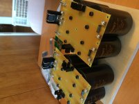
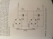
I had some time. Pictured are +/-150 volt supplies for Mosfets. I’m Getting closer. I have 600vdc for the output tube B+. Regulated screen supply. +/-150vdc for the mosfets. I can take the B+ for the driver board from either half the output B+ or maybe better rail to rail of the mosfet supply. I hope to be able to try out a complete bread board amp soon
Evan
Attachments
Spent most of the last few days on the phone with the health care marketplace or the IRS. I still can't file my taxes due to missing documents. Total incompetents are costing me money.
I'm at an outdoor family function today with only phone internet.
The power supply from the SSE should run the driver board and a pair of output tubes up to about 50 watts. You will still need the bipolar mosfet supply.
The driver board needs about 400 volts or more to drive big tubes to fill power. It will eat 600 volts but I haven't tried much more.
I hope everyone had a nice holiday weekend. Mostly I spent time with family but I did take a few hours for myself.
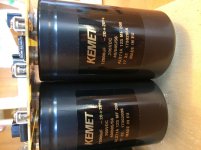
I tested all the power supplies into loads that should be close to the actual draw. Yes there was smoke from the load resistors.
B+ holds at 600VDC this is using two antek 2t230 transformers in parallel.
For the mosfet supply I get 330volts rail to rail.
I tried my screen regulators and no problem regulating the 330 VDC mosfet supply.
Next question. What about elevating the heater supplies? I have built a couple aikido amps both a preamp and a moskido power amp in these I used a simple voltage divider from the B+ supply. Is this the best way?
Thanks and all the best,
Evan
I used a simple voltage divider from the B+ supply. Is this the best way?
That's the way I have always done it. There are some fancy solid state circuits for the purpose, but I can't see the need. The first tube has it's cathodes near ground, and the second tube will have it's cathodes in the 100 to 150 volt range. The heaters should be elevated to about 75 volts.
With caps like those the amp will probably play for a day or two after you turn it off! Just make sure that the screen supply goes down BEFORE the plate supply. I already killed a new KT88 by accidentally knocking the plate supply plug out of the power supply. The screen grid tried to eat all the cathode current and evaporated in a flash of light.
I have most of the parts on order for the boards. I think I'll play around with some 6P41S to see what they can do when I get the boards built.
My translation of the datasheet shows 60W at Va=500 and Vg2=170 for class B, but gives no data for AB1 or AB2, so it is into the unknown.
I think I will try AB1 UL first at a reasonable 250 for Va and work my way up from there.
I have done a couple of SE amps with Va=250 UL and triode mode and they seem to be fine with that.
Spent the day smoking salmon. It keeps going out and doesn't draw for sh*t.

Rolled it too tight......
![DSCN3056[1].jpg](/community/data/attachments/613/613261-78faebd663c266788beec3ace8ed1532.jpg)
Parts are coming in. I think I will try the 6P41S first and see just what I can wring out of a pair.
I'm hoping for something on the far side of 30W, my limitations will probably be my transformers.
IIRC, I have a set of 45W 6K6 Edcore transformers that should be suitable for flogging the tubes.
I'm hoping for something on the far side of 30W, my limitations will probably be my transformers.
IIRC, I have a set of 45W 6K6 Edcore transformers that should be suitable for flogging the tubes.
Happy Friday. I hope everyone had a good week. I am getting one channel wired and would feel much better if I could get confirmation that I have things hooked up correctly. Plus I have a couple questions.
First, and this is a broad one, I’m not sure about the adjustments on the driver board.... I assume r4 and 13 adjust current in first and second tubes. R37 and 43 adjust output bias. No guess for r10
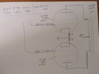
This one may be simple but is a bit confusing to me. Since my B+ is really a +/- supply do I call the -300vdc “ground” or are the 0 volt of the B+ and the mosfet supplies ground? My concern is where to reference the cathodes of the output tubes.
Sorry for not being more self sufficient but I am learning as I go.
Thanks Evan
First, and this is a broad one, I’m not sure about the adjustments on the driver board.... I assume r4 and 13 adjust current in first and second tubes. R37 and 43 adjust output bias. No guess for r10
This one may be simple but is a bit confusing to me. Since my B+ is really a +/- supply do I call the -300vdc “ground” or are the 0 volt of the B+ and the mosfet supplies ground? My concern is where to reference the cathodes of the output tubes.
Sorry for not being more self sufficient but I am learning as I go.
Thanks Evan
Attachments
do you have an outline drawing
Got home late. I have this already made. It is the solder mask layer. M1 through M4 are the mounting holes. The tube sockets have tiny dots for their centers, but your hole diameter will depend on the sockets you have. I have 3 different size sockets in my collection.
Sorry for not being more self sufficient but I am learning as I go.
At this stage of the game ALL questions are valid and will be used when it's time to write the final assembly instructions for the board. Chances are foe every question, there is someone else out there with exactly the same thoughts. Since I have been tinkering with this design for 10 years, I probably figured some of this out years ago and don't even think about it any more.
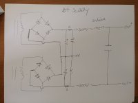
Since my B+ is really a +/- supply do I call the -300vdc “ground” or are the 0 volt of the B+ and the mosfet supplies ground?
It makes no difference what you call something as long as it's wired up right. For the sake of everybody, we will adopt the same convention used by most every tube amp design on the planet.
Note that the solid state world usually calls the connection between the two supplies ZERO, and the extremes PLUS something, and MINUS something. They have P type silicon, and N type silicon, so this makes sense. We only have N type tubes, so we use only positive voltages except for the bias supply. This would make the most negative of your stacked supplies 0 VOLTS and also called GROUND, the center connection +300 VOLTS, and the top of the stack +600 volts. The cathodes of the output tubes would be connected to the 0 VOLT terminal, the screen grid regulator could be fed by the +300 VOLT supply, and the OPT CT is wired to the +600 VOLT terminal. This way all voltage readings would be referenced to GROUND. The input to the screen regulator would be at +300 volts, with 250 volts on its output, and the plates would be at 600 volts.
The mosfets are silicon life forms, and we follow the solid state convention with them. The center of the stacked mosfet supplies is connected to ground, the same ground called zero volts in the main B+ supply. The bottom of the stack will be called -165 VOLTS and will be connected to MOS 3. MOS 2 is the GROUND which is the center of the stacked supply. MOS 1 is +165 VOLTS and is connected to the top of the stacked mosfet supply.
I’m not sure about the adjustments on the driver board
I start with a board containing no tubes, but wired up, no output tubes in place either. Power everything up and check that you have your screen voltage at the output tube sockets. Measure the voltage at each output tube grid and turn R37 and R43 to verify the the voltage can be adjusted over a range of negative voltages with the most negative voltage being enough to cut off your chosen output tube.
Pot R10 is an offset adjustment. it compensates for imbalance between the sections in the tubes. Probe pin 7 of the empty V1 socket. R10 should cause pin 7 to swing from about 1 volt negative to 1 volt positive depending on your meter's internal resistance. The exact voltage is not important as long as it swings on either side of zero. Set it somewhere close to zero volts.
R4 and R13 do adjust the current through the tubes, however it's easiest to set them by adjusting for plate voltage.
Power down, install V1 only, then power back up. Allow for some warm up time and probe the plate voltages. These are easiest to probe on the right hand ends (viewed from the top with silkscreen writing correctly oriented) of R6 and R7. I set these with R4 for about 100 - 110 volts with a 450 volt supply, around 120 volts for 500 volts, so I'm guessing you are looking at 140 to 140 volts. Readjust R10 so that both voltages are equal.
Power down, install V2, power up, wait for warm up, then adjust R13 for about 450 volts on the plates of V2. (ends of coupling caps closest to V2). Readjust R10 for equal voltages on V2's plates.
Install the output tubes, set the bias by measuring the voltage across the 1 ohm cathode resistors.
This should get you operational. These pots can be tweaked for minimum distortion if measurement equipment is available. All adjustments interact somewhat, and the distortion should be optimized at where your average listening level is, not max power since you rarely hit max power. I aim for about 5 watts with 87 dB speakers.
Attachments
IT LIVES... Worked as expected. I followed the set up instructions George outlined in post #178. All of the voltages fell right into place. I can't thank Tubelab enough for taking the time to help me along.
I am not sure how much bias current to let flow. I set 35mA as a start.
I still need to wire a second channel and then the most time consuming part...making the two chassis.
Thanks again,
Evan
I am not sure how much bias current to let flow. I set 35mA as a start.
I still need to wire a second channel and then the most time consuming part...making the two chassis.
Thanks again,
Evan
- Home
- More Vendors...
- Tubelab
- Tubelab Universal Driver Board, 2015 version