UD build questions (1j KT-88s uL & (2) 6AV5 Drive
I have a handful of Universla Driver (UD) Boards coming from George.
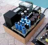
Won’t be starting in them for a little bit, as I have one TSE-II monoblock on Final Approach, and the other one kitted. Oh, yeah, and an 80% finished Pete Millett monster power supply.....
Damned ADD.
HOWEVER, wanted to ask some UD questions EARLY, while I’m still checking inventory for a Mouser order, and to give y’all some time to COGITATE.
(1) Suggested operating points for a UD KT-88 running in Ultralinear?
I don’t need earth shattering wattage as (a) I am a pensioner who startles easily, and (b) all my speakers are well north of 90dB/W (and a couple pairs would have to get new tweeters over 12 watts). 30-40 watts, clear as a bell, with “did the earth move for you too Little Rabbit” bass would be fine.
(2) Operating points for SCREEN DRIVE 6AV5s, plus OPT suggestions?
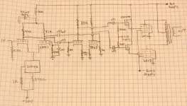
See ancient George schematic sketch attached (which is remarkably close to how the “2015” UD looks, BTW)
I have been haunted by this sketch for better part of a decade, so want to do something about it while I still can. Any suggestions/advice/words of warning (e.g. where to put the FUSES) would be welcome.
BTW, I have Two Sets of unused HANDWOUND push-pull OPTs; I believe I was one of the “lucky” ones that actually received what I ordered from David Lucas, Prince of Darkness (no, wait, that was JOSEPH Lucas, sorry), but of course only after filing a Mail Fraud complain with the USPS...
One set is nominally 60W 6600 ohms, which I suppose could be 3300 ohms if I put 8 ohm speakers on the 16 ohm tap (I think I remember that right...)
It would be nice to use the damned things after all these years, assuming they don’t make big sparks and disappear in a cloud of smoke. The Handwound SE OPTs I’ve used have been quite good, so fingers crossed.
I have a handful of Universla Driver (UD) Boards coming from George.
Won’t be starting in them for a little bit, as I have one TSE-II monoblock on Final Approach, and the other one kitted. Oh, yeah, and an 80% finished Pete Millett monster power supply.....
Damned ADD.
HOWEVER, wanted to ask some UD questions EARLY, while I’m still checking inventory for a Mouser order, and to give y’all some time to COGITATE.
(1) Suggested operating points for a UD KT-88 running in Ultralinear?
I don’t need earth shattering wattage as (a) I am a pensioner who startles easily, and (b) all my speakers are well north of 90dB/W (and a couple pairs would have to get new tweeters over 12 watts). 30-40 watts, clear as a bell, with “did the earth move for you too Little Rabbit” bass would be fine.
(2) Operating points for SCREEN DRIVE 6AV5s, plus OPT suggestions?
See ancient George schematic sketch attached (which is remarkably close to how the “2015” UD looks, BTW)
I have been haunted by this sketch for better part of a decade, so want to do something about it while I still can. Any suggestions/advice/words of warning (e.g. where to put the FUSES) would be welcome.
BTW, I have Two Sets of unused HANDWOUND push-pull OPTs; I believe I was one of the “lucky” ones that actually received what I ordered from David Lucas, Prince of Darkness (no, wait, that was JOSEPH Lucas, sorry), but of course only after filing a Mail Fraud complain with the USPS...
One set is nominally 60W 6600 ohms, which I suppose could be 3300 ohms if I put 8 ohm speakers on the 16 ohm tap (I think I remember that right...)
It would be nice to use the damned things after all these years, assuming they don’t make big sparks and disappear in a cloud of smoke. The Handwound SE OPTs I’ve used have been quite good, so fingers crossed.
Attachments
30-40 watts, clear as a bell, with “did the earth move for you too Little Rabbit” bass would be fine.
Any suggestions/advice/words of warning (e.g. where to put the FUSES) would be welcome.
So your requirements went from 1 MILLION WATTS, to 30-40? Well that's a bit easier. At power levels below 50 WPC I would use conventional control grid drive pentode operation on a 6AV5 to avoid blasting the screen grid, or triode wired KT88's. Some feedback will be needed on pentode mode operation, and a bit more feedback is needed for screen grid drive to keep the output impedance of the tubes down. This is important with less than stellar OPT's.
75 watt per channel triode mode tube amp prototype - YouTube
Fuses should be placed in the cathode lead of the output tube, unless you have fuses rated for use on 600 volts DC. An ordinary 250 VAC glass or ceramic fuse will explode when it sees a short on DC current. I learned this the hard way. A fuse in the cathode should cutoff the tube before the voltage gets high enough to explode the fuse.....except in a tube arc.
BTW, I have Two Sets of unused HANDWOUND push-pull OPTs; I believe I was one of the “lucky” ones that actually received what I ordered from David Lucas, Prince of Darkness (no, wait, that was JOSEPH Lucas, sorry), but of course only after filing a Mail Fraud complain with the USPS...
One set is nominally 60W 6600 ohms, which I suppose could be 3300 ohms if I put 8 ohm speakers on the 16 ohm tap (I think I remember that right...)
It would be nice to use the damned things after all these years, assuming they don’t make big sparks and disappear in a cloud of smoke. The Handwound SE OPTs I’ve used have been quite good, so fingers crossed.
I got two sets of OPT's from that con artist before he blocked me from bidding on his Ebay auctions because "I loose moiney on you."
I threw minimum bids on several of his auctions, won a pair of "10 K ohm SE OPT's for 211 or 845 tube." These are actually better than Hammonds 1628SE (not SEA) were at the time. They are in my 845 SE amp which is still in storage. The other win was a pair of 60W 6600 ohm P-P OPT's, probably like yours. I tried them in a SPP amp, and in the push pull KT88 amps that I was making at the time and they were no better than the smaller cheap Shumaker guitar amp OPT's that I have lots of.
I did drag them out of the box of dead projects for some torture testing recently, but haven't fired them up yet. 3300 ohms with an 8 ohm load on the 16 ohm tap works great on the Schumakers. Don't think I tried it on the Lucas bombs. I have two sets of 3300 ohm 100W Edcors, so that's what I'll put in my amps.
Attachments
George: is there a technical reason to NOT run Ultra-Linear with the UD board?
UL would eliminate the need for a screen power supply, but is there a reason why one would want a separate, presumably adjustable screen supply?
For that matter, could you install a POT between the plate lead and the ultra linear lead (e.g a voltage divider) and “tune” between triode and ultra linear? I guess that wouldn’t work as you wouldn’t be varying the impedance; never mind, need to go back and re-read Hafler.
I assume that you’ve tracked-back through the circuit looking for where the smoke leaked-out. Curious what y’all found.
Had a family issue which took me away from the issue. Last posting on the subject was on AudioKarma in mid-January. May want to check that; A/K user name is same as here.
UD Board Questions: Feedback Wiring, LM4041, etc
I'm fixin' to build-out one UD board, and breadboard it with 6L6s in Ultralinear to wring it out before I cut wood & steel.
Not that I'm particularly fond of the 6L6 family, but
(a) I have a good number,
(b) I have a wide variety , from Sovteks and Shuggies to NIB OEM USA 5881s and 6L6GCs,
(c) they work pretty well in UL, which I like & which obviates need for a screen supply, and
(d) I have a good sampling of 6L6 OPT iron, including ONE hulking OPT from a Heathkit 4AM amp. Which is to say, several SETS of OPTs, albeit nothing capital-A Audiophile.
I'm making a Mouser order for the bits I don't have.
Questions:
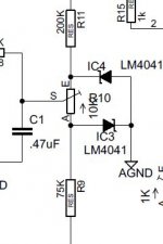
(1) LM4041 Shunt Voltage Reference
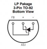
The schematic shows a Zener-like symbol for the two LM4041s (ie TWO leads and a cathode indicated) but the data sheet reveals that the LM40401 is a TO-92-3, ie THREE leads including anode, cathode, and a feedback lead.
Do I assume correctly that we're using the anode & cathode, but NOT the feedback (FB) lead?
Is there a Zener which would substitute? Oops, Output Voltage = 1.225 volts; don't know if there's a discrete Zener with that rating, and if there is, I don't have one anyway. Never Mind.
(2) Single-Point Terminals for Later Tinkering
I like to use single-point solder-in screw terminals wherever a component will likely change. The following should definitely get screw terminals:
(a) C1, in case I want to add Feedback
(b) coupling caps C6 & C7; I always do that
(c) 10M45 current-setting resistors R3 & R12 (now 100ohms, which looks like ~25mA on the graph) in case driver tubes are changed
The following PROBABLY should get screw terminals (?), at least for a breadboard build:
(d) MOSFET supply resistors R9 & R11, and current set resistors R30 & R38?
(e) ALL FIVE of the Plate Resistors (including R223 between tubes)?
I wonder is it wouldn't be better to pick plate resistors for the LOWEST anticipated B+, then add a resistor in series (say at the B+ terminal)
(f) "experimental feedback resistors"
I was going to leave these "slots" empty for the time-being. Any issues with that?
Anything else?
At some point, "total flexibility" becomes self-defeating when the cost of all these screw terminals (and the risk of a LOOSE one) is greter tahn the cost of another board.
Looks like I need to build the first board for a particular B+ (say 400v or 450v) and then a lot of values cascade from that decision. Is that right?
(3) P/S Rectifier
Are folks using tube rectifiers with the UD board? At the power levels folks are talking about, I assume S/S rectification is a better idea. Besides, DYNACO couldn't have been wrong...
(4) Monoblock vs. Stereo
Similarly, this looks like a good application for mono-blocks.
Is anyone building a stereo version, and if so with what power supply?
I'm fixin' to build-out one UD board, and breadboard it with 6L6s in Ultralinear to wring it out before I cut wood & steel.
Not that I'm particularly fond of the 6L6 family, but
(a) I have a good number,
(b) I have a wide variety , from Sovteks and Shuggies to NIB OEM USA 5881s and 6L6GCs,
(c) they work pretty well in UL, which I like & which obviates need for a screen supply, and
(d) I have a good sampling of 6L6 OPT iron, including ONE hulking OPT from a Heathkit 4AM amp. Which is to say, several SETS of OPTs, albeit nothing capital-A Audiophile.
I'm making a Mouser order for the bits I don't have.
Questions:
(1) LM4041 Shunt Voltage Reference
The schematic shows a Zener-like symbol for the two LM4041s (ie TWO leads and a cathode indicated) but the data sheet reveals that the LM40401 is a TO-92-3, ie THREE leads including anode, cathode, and a feedback lead.
Do I assume correctly that we're using the anode & cathode, but NOT the feedback (FB) lead?
Is there a Zener which would substitute? Oops, Output Voltage = 1.225 volts; don't know if there's a discrete Zener with that rating, and if there is, I don't have one anyway. Never Mind.
(2) Single-Point Terminals for Later Tinkering
I like to use single-point solder-in screw terminals wherever a component will likely change. The following should definitely get screw terminals:
(a) C1, in case I want to add Feedback
(b) coupling caps C6 & C7; I always do that
(c) 10M45 current-setting resistors R3 & R12 (now 100ohms, which looks like ~25mA on the graph) in case driver tubes are changed
The following PROBABLY should get screw terminals (?), at least for a breadboard build:
(d) MOSFET supply resistors R9 & R11, and current set resistors R30 & R38?
(e) ALL FIVE of the Plate Resistors (including R223 between tubes)?
I wonder is it wouldn't be better to pick plate resistors for the LOWEST anticipated B+, then add a resistor in series (say at the B+ terminal)
(f) "experimental feedback resistors"
I was going to leave these "slots" empty for the time-being. Any issues with that?
Anything else?
At some point, "total flexibility" becomes self-defeating when the cost of all these screw terminals (and the risk of a LOOSE one) is greter tahn the cost of another board.
Looks like I need to build the first board for a particular B+ (say 400v or 450v) and then a lot of values cascade from that decision. Is that right?
(3) P/S Rectifier
Are folks using tube rectifiers with the UD board? At the power levels folks are talking about, I assume S/S rectification is a better idea. Besides, DYNACO couldn't have been wrong...
(4) Monoblock vs. Stereo
Similarly, this looks like a good application for mono-blocks.
Is anyone building a stereo version, and if so with what power supply?
Attachments
Addendum: just noticed that in 2015
(in the related 6L6GC AB2 thread; 6L6GC AB2 Amp)
that George mentioned eliminating the LEDs in the offset adjustment circuit and substituting a TI voltage Reference IC (presumably the LM4041); the 1.225V Output Voltage makes good sense in the LED context.
SO, can somebody please confirm that I use only the (+) and (-) pins, and NOT the FB pin on the LM4041?
Addendum #2
In the same thread, George said:
"The resistors connected to the FB1 and FB2 terminals allow for plate to plate feedback. They will be connected to a similar set of resistors on the output board. Multiple series connected resistors are needed due to the voltages present on the plates in big power tube output stages.....over 2KV! If you don't need this, just leave them out."
I'll leave 'em out.
UD Output Tube Cathode Fuses?
I like the idea, but what fuse value? 110% of OEM Ik? 150%?
Fast-Blo, I assume.
Seem to recall that CERAMIC fuses are supposed to blow with less chance of shrapnel; dunno if that's true...
Fuses should be placed in the cathode lead of the output tube, unless you have fuses rated for use on 600 volts DC. An ordinary 250 VAC glass or ceramic fuse will explode when it sees a short on DC current. I learned this the hard way. A fuse in the cathode should cutoff the tube before the voltage gets high enough to explode the fuse.....except in a tube arc.
I like the idea, but what fuse value? 110% of OEM Ik? 150%?
Fast-Blo, I assume.
Seem to recall that CERAMIC fuses are supposed to blow with less chance of shrapnel; dunno if that's true...
The schematic shows a Zener-like symbol for the two LM4041s (ie TWO leads and a cathode indicated) but the data sheet reveals that the LM40401 is a TO-92-3, ie THREE leads including anode, cathode, and a feedback lead.
(4) Monoblock vs. Stereo
Similarly, this looks like a good application for mono-blocks.
Is anyone building a stereo version, and if so with what power supply?
My schematic, which is actually an LTSpice simulation, has the LM4041 as a 3-terminal device.
The UDB is capable of driving output tubes to high power. That means big power and output transformers. I hate moving heavy amps around both during building and after building so I'd recommend mono blocks.
I spent a lot of time simulating lots of different anode resistor values and operating points trying to optimise THD. Eventually I realised that George did a great job of specifying the anode resistors and operating points.
My current plan is to rebuild (how many amps does one person actually need?) a couple of 6550 Williamson-style amps with UDBs with component values and operating points as specified and recommended.
I did a lot of simulation and actual testing of the UDB with 6HJ5s in crazy drive. The results were very disappointing.
Attachments
Not that I'm particularly fond of the 6L6 family, but
(a) I have a good number,
(b) I have a wide variety , from Sovteks and Shuggies to NIB OEM USA 5881s and 6L6GCs,
(c) they work pretty well in UL, which I like & which obviates need for a screen supply, and
(d) I have a good sampling of 6L6 OPT iron, including ONE hulking OPT from a Heathkit 4AM amp. Which is to say, several SETS of OPTs, albeit nothing capital-A Audiophile.
6L6GC's and other members of the 6L6 family tree was where I started having enough money to buy tubes as a kid. The local "Eagle Army Navy" surplus / retail store sold Thoro Test 6L6GC's for 99 cents each. They were in reality GE's from reject lots. I sold all my good 1625's and 807's at a hamfest several years ago rather than pack them all up to move 1200 miles. There were several hundred 1625's still in their military boxes from the late 40's.
I did keep a box full of crusty well used 6L6G's, 6L6GA'a and 5881's. A few of them met the UD board starting in post #56 of this thread.
So what happens when the dumm blonde decides to see how much he can squeeze out of a 70+ year old set of 6L6GA's?
Post#58 and some extra undocumented testing revealed that the amp will play well at 100 WPC. I had it running with music for several hours without issue just hitting clipping on peaks into speakers. The "blow up" point is somewhere between 113 watts and 125 watts. Not bad for old tubes.
The failure mode however was a tube arc. Both times it took out the cathode resistor WITHOUT damaging the tubes or OPT.
I'm making a Mouser order for the bits I don't have.
Questions:
(1) LM4041 Shunt Voltage Reference
The schematic shows a Zener-like symbol for the two LM4041s (ie TWO leads and a cathode indicated) but the data sheet reveals that the LM40401 is a TO-92-3, ie THREE leads including anode, cathode, and a feedback lead.
Do I assume correctly that we're using the anode & cathode, but NOT the feedback (FB) lead?
Is there a Zener which would substitute? Oops, Output Voltage = 1.225 volts; don't know if there's a discrete Zener with that rating, and if there is, I don't have one anyway. Never Mind.
(2) Single-Point Terminals for Later Tinkering
I like to use single-point solder-in screw terminals wherever a component will likely change. The following should definitely get screw terminals:
(a) C1, in case I want to add Feedback
(b) coupling caps C6 & C7; I always do that
(c) 10M45 current-setting resistors R3 & R12 (now 100ohms, which looks like ~25mA on the graph) in case driver tubes are changed
The following PROBABLY should get screw terminals (?), at least for a breadboard build:
(d) MOSFET supply resistors R9 & R11, and current set resistors R30 & R38?
(e) ALL FIVE of the Plate Resistors (including R223 between tubes)?
I wonder is it wouldn't be better to pick plate resistors for the LOWEST anticipated B+, then add a resistor in series (say at the B+ terminal)
(f) "experimental feedback resistors"
I was going to leave these "slots" empty for the time-being. Any issues with that?
Anything else?
At some point, "total flexibility" becomes self-defeating when the cost of all these screw terminals (and the risk of a LOOSE one) is greter tahn the cost of another board.
Looks like I need to build the first board for a particular B+ (say 400v or 450v) and then a lot of values cascade from that decision. Is that right?
(3) P/S Rectifier
Are folks using tube rectifiers with the UD board? At the power levels folks are talking about, I assume S/S rectification is a better idea. Besides, DYNACO couldn't have been wrong...
(4) Monoblock vs. Stereo
Similarly, this looks like a good application for mono-blocks.
Is anyone building a stereo version, and if so with what power supply?
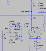
1) The LM4041 devices have three pins, and should be inserted in the board according to the silkscreen. The feedback pin has no connection in this application. These have a well defined temperature characteristic, which cancels in this application, keeping the offset voltage constant over temperature. The previous LED's wandered a bit when warmed up.
2) You can use single pin terminals wherever you wish, but they are not needed for R3 and R12 since they are in series with a pot, and only limit the current to a MAX of 25 mA. The pot allows for an adjustable amount of less current. Feedback can be applied in series with C1, but should be capacitor coupled to avoid affecting the offset null circuit.
Leave the feedback resistors out unless you want to experiment with them. If used, space them at least 1/4 inch above the board, AND use an external series resistance. The voltage swing at the plate of the output tube can be over 2KV. Most resistors can not eat this much, as I learned the hard way back in post#117. That left a hole burned in the board and a magnetized OPT.
The values given in the parts list have been used for B+ voltages from 350 volts to 650 volts. Running less than 350 volts may take some value tweaks. All of my testing has been done with 6CG7 / 6FQ7 tubes since they are just shrunken 6SN7's which is what this designed started with back in 2008 or so. A different tube lineup may require different resistor values.
A tube rectifier will work OK up to a point where the voltage / current requirements get too high. A 5AR4 will drive a push pull pair of 6L6GC's at 35 WPC with no problem. 50WPC is a maybe....I haven't tried it.
I tested my board with triode wired 6550's on a big power supply to determine the AVERAGE current requirements at 75 WPC. it is beyond the reach of a 5AR4.
That amp draws about 225 mA at idle, and 600 mA when making 150 watts of sine wave. Cranking some TSO at the edge of clipping kept the needle centered around 350 mA. This would require sand or two rectifier tubes.
A mono block should work fine with a single 5AR4.
Attachments
DCH53:
Re: "How many amps does one person need?"
Entire religions have been built around this question. Well, cults anyway.
I believe that the answer is One Per Room, plus one on the bench at all times, and 3-6 on the shelf.
It's up to you whether you put an amp in the "powder room."
Beyond that, you need to start lending them out.
Last edited:
"Re: "How many amps does one person need?"
Entire religions have been built around this question. Well, cults anyway.
I believe that the answer is One Per Room, plus one on the bench at all times, and 3-6 on the shelf.
It's up to you whether you put an amp in the "powder room."
Beyond that, you need to start lending them out."
A person needs one amp per room, and then one amp per room at the workplace.
UD Trimmer Pots OBSOLETE
The Bourns trimmer pots in the UD BOM
3309P-1-102 1K
3309P-1-104 100K
are obsolete: https://www.bourns.com/docs/technical-documents/product-obsolescence-memos/T1809_3309_3319_POM.pdf
Does anyone know of a replacement part with 5mm x 10mm lead spacing?
Can't search the Mouser/Digikey databases for lead spacing AFAIK, so unless somebody has already found substitutes, I will have to wade through the datasheets...
3309P-1-102 1K possible substitute:
https://www.mouser.com/ProductDetai...ctronics/37PR1KLF?qs=QwqSU04NtKl5wARv5wfZ/A==
I'll stick it in the cart and double check in the daylight...
https://www.mouser.com/ProductDetai...ctronics/37PR1KLF?qs=QwqSU04NtKl5wARv5wfZ/A==
I'll stick it in the cart and double check in the daylight...
The 100K version (3309-1-104 substitute):
37SR100KLF BI Technologies / TT Electronics | Mouser
37SR100KLF BI Technologies / TT Electronics | Mouser
Don't you love it when a part for one of your designs goes extinct?
In this case no scrambling to find a replacement is needed as the footprint is pretty common.
Use the Piher pots from the same series as found in the TSE-II BOM. I find these on the surplus market from time to time and buy 100 whenever I find them just so I won't need to recycle pots from my test boards and experiments which often have lots of pots. The footprint on the board is actually from a Piher pot. They were real common in the US back in the 80's and 90's, then vanished so I switched to the Bourns pots. Piher returned to Mouser several years ago.
I have been working on a vacuum tube powered music synthesizer. My tube breadboard of the famous Moog ladder filter currently has about 20 pots on it and still doesn't work right.
George: The PIHER/Amphenols from that series (PCT-10) aren't available in 1/2W (500mA) like the specified Bourns trimpots, only 1/3W.
Does it matter?
Just don't want to let the smoke out.
Cheaper, sleazy looking trimpots at 1/2W and 100 deg C for ~$0.50
<or>
Nice looking PIHER/Amphenol trimpots at 1/3W and 90 deg C for ~$1.50.
Does it matter?
Just don't want to let the smoke out.
Cheaper, sleazy looking trimpots at 1/2W and 100 deg C for ~$0.50
<or>
Nice looking PIHER/Amphenol trimpots at 1/3W and 90 deg C for ~$1.50.
George: The PIHER/Amphenols from that series (PCT-10) aren't available in 1/2W (500mA) like the specified Bourns trimpots, only 1/3W. Does it matter?
Just don't want to let the smoke out.
The pots are used to set the gate voltage on a mosfet. This becomes the bias voltage for the output tubes.
The resistor values shown on the schematic were chosen when I was using the UD board for a screen drive experiment. The bias voltage was always POSITIVE, and not what you would use on a typical UL amp.
In the typical G1 driven triode / UL / pentode mode amp the bias voltage would be adjustable over a range of negative voltages. The values of the resistors connected to the pots determine this bias range and are tube dependent. In any case the resistor values are chosen such that about 1 mA or less of current flows through the pot, given a bias adjustment range of less than 100 volts. This would subject the pot to less than 100 mW of power making even a 1/4 watt pot suitable.
PS WHAT, no Thermionic THEREMIN?
I built a vacuum tube Theremin from some plans in a electronics magazine back in the late 60's or early 70's. This was at the peak of my guitar playing ability, but I never could play that Theremin, so I wound up giving it away.
The dexterity and control of my hands has gotten worse, especially in the last few years, to the point where playing the guitar is futile. Playing a Theremin would involve a lot of vibrato at best, but probably just generate noise.
I now spend more time correcting mistakes than I do typing. Some days are worse than others, and sometimes I get frustrated early and just turn the computer off.
I am also trying to finish all of the small boards that use tiny leaded and SMD parts for the synthesizer while I can still solder them. In my last few years at Motorola I often got a lab tech to solder the 0204 stuff for me....and he was older than me.
- Home
- More Vendors...
- Tubelab
- Tubelab Universal Driver Board, 2015 version