Hi,
I was going through the gallery of Tubelab amps built by diyA members. Unfortunately some of the pics are no longer visible due to broken links.
One thing I noticed that the most common style of switches are toggle type ones. I've used rocker type switches, and I guess others use that too. What about latching switches - something like this?
22mm Waterproof 12V Self locking or Reset ring illumination Black Latching Anti vandal push button switch-in Switches from Home Improvement on Aliexpress.com | Alibaba Group
Would this be a safe/good choice? Any concerns with in-rush current or plate voltages?
I use a round rocker, with an outline LED illumination, for the AC mains on my SSE. It's been trouble free.
If you want a latch switch, that switch seems like it would be fine - it's rated for 5 amps at 220VAC, and claims 2000 volt insulation. You can get the LED ring in about any color or voltage up to 220 volts.
One thing that is a little unclear to me, is the actual operation of the LED itself. The LED in my switch runs right off the AC main voltage, without rectification. The schematic for that switch shows a series resistor, but nothing else, so you may need some additional circuitry.
Win W5AG
edit: price may be a bit high - not sure of parts availability in Bangladesh. I pay about that for a similar switch at Radio Shack. I would expect it to be a bit cheaper when the middlemen are out of the distribution system.
I guess I need to order some more - the type I use has been marked down to $2 USD from $7 USD. RadioShack SPST 125-Volt AC Illuminated Switch
Last edited:
Bumping this along...
Would like to add a power switch/button on the front panel. This is in addition to a switched IEC power entry module at the rear of the chassis. What's the required spec for the power switch and IEC module? I'm in the US, so I suppose anything rated at over 120VAC would work. But how many amps min? 2A? 5A? More?
Interestingly, there are tons of cool push-button switches that run low DC voltage and amps. Probably unrealistic, but might there be a practical way to use one of these? Perhaps with a SS relay or something?
Check out AMB's switch driver. I have built a couple. Very elegant solution!
The ε24 power switch driver circuit
Me
The ε24 power switch driver circuit
Me
Check out AMB's switch driver. I have built a couple. Very elegant solution!
The ε24 power switch driver circuit
Me
The ε24 power switch driver circuit
Me
Check out AMB's switch driver. I have built a couple. Very elegant solution!
The ε24 power switch driver circuit
Me
muskyhuntr - looks like the AMB Epsilon24 uses momentary switches and not latching switches?
Check out AMB's switch driver. I have built a couple. Very elegant solution!
The ε24 power switch driver circuit
Me
muskyhuntr - looks like the AMB Epsilon24 uses momentary switches and not latching switches?
The e24 looks like a great solution. I had a cool button in mind, but after looking at the dimensions more carefully, it won't mount on a 10mm thick panel. This button and other like it are designed to fit ~6mm max. I suppose one solution is to machine the backside of the panel and thin out the mounting area to 6mm or less, but the extra cost and complexity has just about killed this idea.
On the other hand, I saw a post where someone used a version of one of these: MSM LA 19 - Metal Switch, Latching Action, Switching Voltage up to 125 VDC / 250 VAC
Switching voltage up to 250VAC and switching current up to 16A. Seems like it should have worked. With a lot less effort. Would a latching SPDT variant do the trick?
I'm in the US, so I suppose anything rated at over 120VAC would work. But how many amps min? 2A? 5A? More?
3 should do it
I've finally found a larger diameter latching pushbutton switch. It's rated at 5A/240VAC. Good to go?
Everyone using 10A rockers is making me nervous and second guess. Thanks.
I want to order this 5A/250VAC switch.
30mm Momentary or latching 1no1nc Ring LED Anti Vandal Push Button Switch 6V, 12V, 24V, 110V, 220V-in Switches from Home Improvement on Aliexpress.com | Alibaba Group
Seems to me it should work but would like some reassurance
30mm Momentary or latching 1no1nc Ring LED Anti Vandal Push Button Switch 6V, 12V, 24V, 110V, 220V-in Switches from Home Improvement on Aliexpress.com | Alibaba Group
Seems to me it should work but would like some reassurance
I realized during final assembly that I don't have specs for the illumination LED on the switch described in my previous post. I've sent an email to the vendor, but in the meantime, I hooked up the switch w/o illumination. Thankfully, the power on/off works as expected.
When I ordered the switch, I assumed it could be installed the same way as the lighted switch on my IEC power entry module. Now I'm not so sure. The pin configuration makes me believe the LED is most likely 5V or 12V DC.
The switch has 6 terminals: 2 for NO, 2 for NC, one +, and one -. Assuming I'm correct about it being DC, any suggestions on how to make the LED connections?
Did you order the switch from the alibaba page from your previous post? If so, most of the specs were in the order page. Depending on what you selected when you ordered, the LED will have a built in dropping resistor for 6v, 12v, 24v, 110v, or 220v. If you selected a lower voltage than you wanted to use, you will need to add another drop resistor and a diode to prevent exceeding the PIV rating of the internal LED.
I also highly recommend installing a RC snubber across the switch contacts if you haven’t already.
I also highly recommend installing a RC snubber across the switch contacts if you haven’t already.
Ah that makes sense. There is some shrink tubing on one of the LED terminals and I think a resistor is hiding underneath. Household voltage is 110v, but I ordered 220v, and the vendor says the LED is rated for 250v.
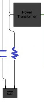
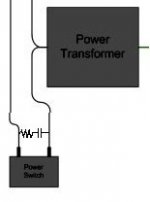
RC snubber sounds like a good idea but I've no idea how to implement. The little I understand from Google searching is that a resistor and capacitor is needed? Would I connect as shown in the image? What values would I use?

RC snubber sounds like a good idea but I've no idea how to implement. The little I understand from Google searching is that a resistor and capacitor is needed? Would I connect as shown in the image? What values would I use?

The 220v version is likely work with 110v, it will just be a little dim.
The snubber is recommended because your power switch will likely live a short an unhappy life without one. More important than anything else, any capacitor placed on the mains must be safety rated for that purpose.
The snubber is recommended because your power switch will likely live a short an unhappy life without one. More important than anything else, any capacitor placed on the mains must be safety rated for that purpose.
Your new diagram looks correct, another way to correctly install a snubber is in parallel with your load (the power transformer). However, your calculated values are off. A common combination is a .1uF X2 safety capacitor in series with a 4.7R 1W resistor.
Most importantly the capacitor needs to be at least X2 rated, this will help avoid catastrophic failure of the capacitor. Older amps commonly used 2500V ceramic capacitors and they were known to occasionally blow apart.
Most importantly the capacitor needs to be at least X2 rated, this will help avoid catastrophic failure of the capacitor. Older amps commonly used 2500V ceramic capacitors and they were known to occasionally blow apart.
- Status
- This old topic is closed. If you want to reopen this topic, contact a moderator using the "Report Post" button.
- Home
- More Vendors...
- Tubelab
- Power switch options
