I've been guilty of loose terminology in referring to this as plate to plate, which is how it is usually drawn on a schematic - a high value resistor connected between the plate of the output tube and the plate of the driver tube.
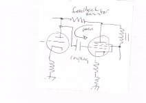
The feedback path is actually from the plate of the output tube, through the coupling capacitor between the driver and output tube, and back into the grid of the power tube, so local plate to grid feedback is the better way of saying it.
The crude drawing may - or may not - help visualize it.
The local plate to grid feedback will work for triode mode, it is not needed, but you might find that you like the way it sounds. I have tried that with the DHT SSE.
I don't know how it would work in combination with UL - I haven't tried it.
I think you would need to have some way of disconnecting the resistor to disable this feedback when you do not want it. I used a terminal block on mine where I can just remove it, and can play around with different values of feedback by changing the resistor. A switch would likely be okay, once you have settled on a value.
Win W5JAG
Attachments
So you connected the resistor from the plate terminal on the board to the the terminal block then a length of wire from the block
soldered to either the plate pin on the driver tube or the coupling cap lead ?
I see you used a 100k resistor, is 1W okay or should I use 2W or 3W ? If I want to fine tune it what increments to use up or down, 5k, 10k ?
soldered to either the plate pin on the driver tube or the coupling cap lead ?
I see you used a 100k resistor, is 1W okay or should I use 2W or 3W ? If I want to fine tune it what increments to use up or down, 5k, 10k ?
Yes.
1 watt should be fine.
I used 100K because I had it and was what I used with the 6146 SSE; I don't stock a lot of 1 watt and up resistors. 100k is a lot of feedback. If you are ordering, I would get the standard values starting at maybe 750K, 680K, 560K, etc., and going down to 100K, listen to them and decide how much feedback you need / want.
I expect different tube types might need more or less feedback than other types.
Win W5JAG
BTW, if you don't have any 6U6's, you might want to try them if you can get some inexpensively.
Last edited:
I assume with the Schade local nfb in place I can revert to Triode/UL without it affecting the sound in any way ?
I had some unexpected time yesterday afternoon, and played around with the local plate to grid feedback, looking at some measurements. I didn't take any notes, just played around with it.
For the most part, the results were expected. I used some Russian 6P3S power tubes, in three combinations: pentode, with 100K local plate to grid feedback, straight triode strapped, and triode strapped with 100K local plate to grid negative feedback, 275 ish on the plate and screens, small 5K Edcors, 12AT7 driver, fixed bias, about 14 watts dissipation.
I found that pentode, with local plate to grid feedback, put out about twice as much power as straight triode, with about twice the distortion, and increased sensitivity ( less drive required ). No surprises there. A lower plate load would probably yield better output at these voltages.
Anyway, what was interesting was triode strapped with the 100K local plate to grid. I expected this would reduce the power output, as I am burning some output sending it back into the grid, but I found the opposite result. Consistently and repeatably, I found that I can get about an extra 0.3 Volts across an 8 ohm load resistor, with the local feedback. My test equipment is mediocre, but I cross checked it, and this is what I got. I tried this with some 5881's, and got the same result. That's not much extra power, about 3/10 of a watt at 8 ohms, but it was not what I expected. THD went down to about 0.6% at 1 watt output, IIRC.
I hooked it back up and listened to it in the triode, local feedback, 6P3S, 12AT7, configuration for several hours. Sounded fine, nothing objectionable that I could tell. The 12AT7 that I am using has mis matched sections - one side has about twice the distortion of the other, both IMD and THD. I am running it at reduced current - that may or may not be a factor. I cannot detect this in ordinary listening, so, non issue as far as I am concerned.
Win W5JAG
That's some interesting info you posted there W5JAG. I should try it when I get the chance.
I'm still recovering from a serious knee injury I sustained last summer. As a result I haven't been
doing much of anything including checking on the forum.
Before my injury I did try the plate to grid feedback you suggested. I had some 130K 2W resistors on hand and
tried these with pentode connection. As you said it does clean up the sound considerably.
I planned to get several different values of resistors to see if I could find a common value suitable for the
different output tubes I have. I also planned to install a switch for switching from pentode connection back to UL/Triode.
Maybe next spring or summer I'll be able to do this stuff.
Thus far I've been using Pete Millet's screen voltage regulator from his Engineer's Amp.
I've been looking at his Maida style voltage regulator for which he sells a pcb on EBay.
As is, his regulator is adjustable for a relatively narrow range of 135 to 156 volts. I wanted to know if it can be
adapted for a wider range so I emailed him about this and got a favorable response.
Here is his response........
" Using standard values, about the closest you could get would be to make R4 10k and RV1 15k.
That would give you an adjust range of about 100V to 260V.
The problem with this, however, is that the power dissipation of RV1 would be as high as 1.6 watts,
which is more than the trimmer pot used on the PCB can handle. So you would have to use a larger pot
wired in off the PCB. Something like this: https://www.digikey.com/product-det...s-corporation/RV4NAYSD153A/RV4N153C-ND/265525
I think I'll give this a try whenever I'm able to do the other stuff.
.... I'm still recovering from a serious knee injury I sustained last summer. As a result I haven't been doing much of anything including checking on the forum. ....
Recovering sounds good, but the still recovering part of that sounds really bad .... hate to hear this happened to you.
Hang in there.
I was working on a building about five years ago, and in a classic my stupidity never ceases to amaze me moment, I spectacularly managed to break my ankle in two places and for extra fun and misery, my heel pretty badly. I had just turned 53 at the time, and we were expecting our third child in about six or seven weeks, and this, that, and all the other things, just made not being able to walk a non starter for me. I told the Doc I would walk back into his office in eight weeks, and against his advice I did, but pretty badly I'll concede, and still carried a crutch as a just in case .....
It was several years before all the morning stiffness, foot pain from the heel, etc., went away, but about three years out, all of it was (is) as strong as it ever was, but my sense of invincibility is tarnished a bit ....
Win W5JAG
- Status
- This old topic is closed. If you want to reopen this topic, contact a moderator using the "Report Post" button.
- Home
- More Vendors...
- Tubelab
- Trying to use Pete Millet's screen voltage regulator in the SSE