My buddy and I have built 2 identical TSE boards. Same parts, PT, choke, etc.
My amp works fine but his the FET's will not turn on and bias the output tubes.
We measured static resistance at D, S & G of FET's, as well as all pins on the 45's and they match within a few ohms. Voltage is obviously higher on his because the 45's aren't conducting.
Mine: FET D=254V, G=-240V to -143V (pot), S=-197V
His: FET D=390V, G=-255V to -232V (pot), S=-298V
We have tried a new set of FET's, swapped power tubes, nothing! Driver's seem to be working fine and set to a plate voltage of 175V.
Any ideas?
What value R14 and R25 is he using?
36K ... same as mine with same power transformer.
Make sure R6 is 10k and measure the voltage drop across it.
To me it looks like your bias supply is too high. Make sure R11 and R22 have a good ground connection, same with R7.
Both amps are 10K at R6.
Mine is: -406V -> R5 -> -402V -> R6 -> -243V
His is: -417V -> R5 -> -416V -> R6 -> -333V
I assumed his was higher because no current was flowing through the FET?
I just wanted to make sure the bias resistors and r7 were pulling current, 8mA should be right.
Continuity test the MOSFET pins (while off). Put one lead on the source pin and the other lead on r14/r25. Then put one lead on the gate pin and the other lead on r15/r26. The PCB traces can lift and have bad connections. I got my TSE board for free and went through the same issue, bad traces was the problem
Continuity test the MOSFET pins (while off). Put one lead on the source pin and the other lead on r14/r25. Then put one lead on the gate pin and the other lead on r15/r26. The PCB traces can lift and have bad connections. I got my TSE board for free and went through the same issue, bad traces was the problem
I just wanted to make sure the bias resistors and r7 were pulling current, 8mA should be right.
Continuity test the MOSFET pins (while off). Put one lead on the source pin and the other lead on r14/r25. Then put one lead on the gate pin and the other lead on r15/r26. The PCB traces can lift and have bad connections. I got my TSE board for free and went through the same issue, bad traces was the problem
All good ... have continuity to the FET's.
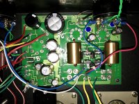
I can but I am not sure how useful that will be as it is installed in a chassis currently so I can only snap a picture of the bottom side ... see attached.
As I mentioned prior, this is a clone of my unit which is working properly and has the exact same components on each board. The only difference is I added a switch to go from 2.5V to 5V filament, a volume control and of course different tubes (but we also have swapped tubes to rule that out as well).
FYI - You'll notice the wires running to the location of R18/R29 ... these run to a 10-ohm shunt mA panel meter (with the resistors removed) so we can set the bias visually without requiring a multimeter.
Attachments
Last edited:
I know that I and others had a problem with a connection between the two sides of the board that was diagnosed by Win W5jag as follows:
Also, the center pin of one of the 10M45's is used to pass voltage between the top and bottom sides of the board; if the solder doesn't plate through the hole, shenanigans occur. It's described on the last page of the 801A in Tubelab SE thread a page or two back.
Win W5JAG
Just a suggestion.
Also, the center pin of one of the 10M45's is used to pass voltage between the top and bottom sides of the board; if the solder doesn't plate through the hole, shenanigans occur. It's described on the last page of the 801A in Tubelab SE thread a page or two back.
Win W5JAG
Just a suggestion.
I know that I and others had a problem with a connection between the two sides of the board that was diagnosed by Win W5jag as follows:
Also, the center pin of one of the 10M45's is used to pass voltage between the top and bottom sides of the board; if the solder doesn't plate through the hole, shenanigans occur. It's described on the last page of the 801A in Tubelab SE thread a page or two back.
Win W5JAG
Just a suggestion.
I checked this today ... I reflowed the center pin of both CCS to ensure a good fillet on top and bottom side of the PCB. I powered it up and one side started rising in bias so I killed power at about 40mA. I pulled all the tubes and reset the initial start-up procedure by setting grid to most negative, installing 5842's, setting their plate and then I installed the 45's and again ... they will not conduct! I can turn the bias pot all the way in both directions and nothing.
I'm about at my wit's end!
There are four possible reasons that the 45's don't conduct. You should be able to test most of this without any output tubes in the board. All observations and measurements are made while looking at the top side of the board from the front (volume pot area towards you, rectifier on the left, output tubes in the back). The black meter lead should be connected to a known good ground.
#1) Dead tubes. You swapped tubes around, so this isn't it.
#2) No plate voltage. There should be B+ on pin 2 of the output tubes (left rear pin).
#3) Filament not glowing. There should be 2.5 volts on pin 1 of the output tubes (right front pin).
#4) Too much negative bias. The voltage on pin 3 should be adjustable over a range from -30 to about -100 volts.
If all of this checks out, make sure that the tube sockets have not been installed such that the pins are rotated 90 degrees. I did this once on an early build and it took me a while to find it.
There are four possible reasons that the 45's don't conduct. You should be able to test most of this without any output tubes in the board. All observations and measurements are made while looking at the top side of the board from the front (volume pot area towards you, rectifier on the left, output tubes in the back). The black meter lead should be connected to a known good ground.
#1) Dead tubes. You swapped tubes around, so this isn't it.
#2) No plate voltage. There should be B+ on pin 2 of the output tubes (left rear pin).
#3) Filament not glowing. There should be 2.5 volts on pin 1 of the output tubes (right front pin).
#4) Too much negative bias. The voltage on pin 3 should be adjustable over a range from -30 to about -100 volts.
If all of this checks out, make sure that the tube sockets have not been installed such that the pins are rotated 90 degrees. I did this once on an early build and it took me a while to find it.
Everything is good except for #4 ...
On my amp which works, my grid swings from -240V to -143V. His is swinging from -255V to -232V with the exact same parts installed, same power transformer, etc.
Is it possible that mine is just on the cusp of having too much negative bias due to component tolerances?
my grid swings from -240V to -143V. His is swinging from -255V to -232V
Is it possible that mine is just on the cusp of having too much negative bias due to component tolerances?
Yes, yours is on the edge of not working. Can you adjust the bias current to at least 50 mA or more?
What output tubes are you using. I somehow thought that you were running 45's which would not conduct at all on these voltages.
-143 volts should cut off even a 300B unless you are feeding it well over 400 volts. -232 volts will cut off any tube that I can think of that fits into a small 4 pin socket.
Yes, I am running CX-345's
My -240V to -143V is no load (without power tubes installed). With load and both biased at 30mA, my B+ is 255V and grid is -24V. I can't get his to conduct, so I can't measure it under load.
Last edited:
Unloaded, you can swing your bias voltage almost 100 volts. He can swing his only about 20.
Sounds like the wrong resistors were installed in the bias dividers of each channel, or they are incorrectly marked as one value, but in fact are some other value.
That's all I can think of. If you haven;t already, start lifting component legs and measuring actual component values of the resistors, and the range of the pots. That will be a PITA given how it is installed, but it seems like you have run out of the easy options.
Win W5JAG
- Status
- This old topic is closed. If you want to reopen this topic, contact a moderator using the "Report Post" button.
- Home
- More Vendors...
- Tubelab
- TSE Help!