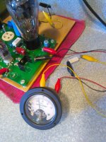
OK, here is one way of doing this. Not the only way.
The SSE pictured has had the cathode resistor R17 removed from the board, and a scrap component lead soldered to each pad for R17. The red clip lead attaches to the pad nearest the bypass capacitor; the opposite end attaches to the positive connection of the milliammeter. The yellow clip lead attaches to the negative connection of the milliammeter; the opposite end attaches to one lead of the cathode resistor. The black clip lead connects the remaining lead of the cathode resistor to the ground pad on the pcb.
Current flows in series through the meter, through the cathode resistor, and then to ground. As shown in the picture, the milliammeter directly reads the cathode current.
To do this on the SSE, lift the end of the cathode resistor nearest the bypass capacitor. Solder an insulated wire to that pad and connect the opposite end to the positive terminal of the meter. Connect an insulated wire to the negative terminal of the meter, and solder the opposite end of that wire to the lead of the cathode resistor previously lifted from the board.
If you are lazy, you can cut the lead, and use each end of the lead as a solder point.
If, for some reason, your meter reads backward, reverse the connections at the meter.
If done correctly, and if your meter is undamaged, your amp will work normally and the meter will display the value of the current passing through the tube.
Win W5JAG
Attachments
It was stated, "Try putting the meters in series with the cathode resistors of the power tubes". Did you lower the value of the cathode resistor to compensate for your meter's internal resistance? Is your meter robust enough to pass the power tube's current continuously?
CAN SOMEONE KNOWLEDGEABLE ON THIS SUBJECT ANSWER THIS? PLEASE
1. I am not particularly knowledgeable.
2. While counter intuitive, the TSE is a fixed bias amplifier. The bias is adjusted to a particular ( usually ) negative voltage, and is expected to remain fixed at that voltage. Hence the name, fixed bias.
3. The SSE is a cathode bias amplifier, it's negative bias is set by the voltage drop across the cathode resistor. This value will change as the plate voltage changes. Some people, including me, also call this self bias. I have also heard people call this automatic bias.
4. Metering the SSE is of limited utility, unless you are going to experiment with it. Then, metering may have some merit.
5. Post #21 should be fairly self explanatory, and in my view is probably the most useful way of metering the SSE. This requires two meters.
There are other ways.
A single series milli ammeter can be placed in the B+ line to measure the current drawn in the entire amplifier.
A voltmeter can be attached to the top of the cathode bias resistor to measure cathode voltage, and one can do the arithmetic to derive cathode current.
6. I don't understand the concerns expressed in post #22. Most milli ammeters don't have much series resistance. In the unlikely event this is an issue, reduce the cathode resistor value to compensate.
I have never seen a meter that cannot handle, on a continuous basis, the maximum current it is designed to meter. If the point is to not use a 25 ma meter to meter 100 ma, then I agree.
7. IMO, capital letters should be used sparingly.
Win W5JAG

There are meters and then there are ….. meters. All electomechanical meters are essentially galvanometers. A voltage potential deflects the arm. I have some military grade ammeters that have very little internal shunt resistance. The mechanical arm is so well balanced that it can respond to the very slight voltage potential across the low ohm shunt. I also have cheap plastic ammeters that have considerable internal shunt resistance. The cheap ones need more resistance to develop a higher voltage potential to move the crappy internals. And if you’re passing all the tube’s current through the shunt in the meter then higher resistance uses more watts & more heat.
Thus my curiosity about the quality of the referenced ebay meters.
If it was me I’d use a voltmeter with a known good shunt resistor. There are reasonably accurate cheap ebay 1 (one) volt meters. If they are wired in parallel with a quality 10 ohm resistor of sufficient wattage. Then using Ohms law 0.01 amps ( 10mA ) of current will show 0.1 volts (100mV). So if you’re looking for say 50mA of cathode current then the meter would say 0.5 volt.
... I’d use a voltmeter with a known good shunt resistor. There are reasonably accurate cheap ebay 1 (one) volt meters. If they are wired in parallel with a quality 10 ohm resistor of sufficient wattage. Then using Ohms law 0.01 amps ( 10mA ) of current will show 0.1 volts (100mV). So if you’re looking for say 50mA of cathode current then the meter would say 0.5 volt.
Sure, that way will also work just fine.
I have converted my two operating SSE's to fixed bias, and that is how I monitor the cathode current in them - in lieu of grounding the cathode, I installed a 10 ohm resistor where the cathode resistor would normally go, and I meter across that with a voltmeter. The power in the 10 ohm resistor is negligible - in the DHT SSE pictured in post #21, I think I am using a 1/4 watt resistor. That amp ran for about a month, continuously, with 2A3's in it at probably 45 - 50 mils, when I was at a different house over the holidays.
If damuffinman just wants to see meters move, he can take some of the output, rectify it, filter ( smooth ) it, might need to be amplified, and apply that to a sensitive voltmeter. There might be kits for that on eBay. Haven't looked.
Win W5JAG
Last edited:
I was thinking of also adding some panels to my TSE, this thread has very helpful information.
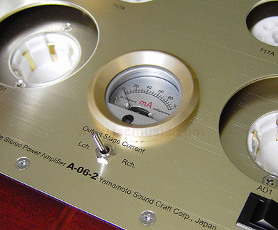
I was looking into the Yamamoto panels on JacMusic website, and there is an interesting solution to use a single meter for both channels with a switch.
These panels are super pricy so that sounds like an interesting compromise.
Although, since current meters are in series, I don't really understand how you can switch the channels without removing the other from the circuit.
Thoughts?
Okay so I've learned that this specific panel meter is connected in parallel, so switching is easy. It can't work with the TSE though since it requires a cathode bias resistor
You really want a voltage meter, and then measure the voltage across R28 and 18.
I added test points on my top panel to provide access to the voltages/bias
Randy
You can't separate the filament circuit of the two output tubes without two separate filament supplies. This would require a custom power transformer (two filament windings) and two rectifier / filter / regulator circuits. Unless you plan to redesign a good part of the amp, the meter must go in the plate circuit.
OK, here is one way of doing this. Not the only way.
The SSE pictured has had the cathode resistor R17 removed from the board, and a scrap component lead soldered to each pad for R17. The red clip lead attaches to the pad nearest the bypass capacitor; the opposite end attaches to the positive connection of the milliammeter. The yellow clip lead attaches to the negative connection of the milliammeter; the opposite end attaches to one lead of the cathode resistor. The black clip lead connects the remaining lead of the cathode resistor to the ground pad on the pcb.
Current flows in series through the meter, through the cathode resistor, and then to ground. As shown in the picture, the milliammeter directly reads the cathode current.
To do this on the SSE, lift the end of the cathode resistor nearest the bypass capacitor. Solder an insulated wire to that pad and connect the opposite end to the positive terminal of the meter. Connect an insulated wire to the negative terminal of the meter, and solder the opposite end of that wire to the lead of the cathode resistor previously lifted from the board.
If you are lazy, you can cut the lead, and use each end of the lead as a solder point.
If, for some reason, your meter reads backward, reverse the connections at the meter.
If done correctly, and if your meter is undamaged, your amp will work normally and the meter will display the value of the current passing through the tube.
Win W5JAG
Thanks for posting these instructions! I'll be using this method on my SSE soon!

- Status
- This old topic is closed. If you want to reopen this topic, contact a moderator using the "Report Post" button.
- Home
- More Vendors...
- Tubelab
- Installing panel meters on an SE