Hello everyone I chose tubelab sse for my very first build because it seemed like it would be totally easy. That was before I bought the board and most of the parts only to find out that the board has been updated (d3 + d4 + tr1) with no mention of it in the parts list. Anyway I read a whole lot of threads to try to catch up and believe I have but being new to diy electronics I still have a few nagging questions.
I am going to use in4007's for d3 & d4 and had already purchased cl90's as per the assembly manual, but I had to order cl140 from ebay cause they don't fit on the Board! Lol
My question is probably dumb, but d3 & d4 are needed as well as the Fred's if I want sse rectification, Correct?
And I read a suggestion for the supplemental power cap to be 100uf motor run capacitor, but that was before I read George's thoughts on it and he suggests the total supplement cap and c2 should be around 150uf. Will the cap I have be okay as 100uf plus the c2 cap on board 120uf is more than that, do I have to buy another motor run capacitors with a lower value?
I think George is a very talented designer but his website maintenance leaves something to be Desired! Lol
Any comments will be Appreciated!
Sent from my SM-T810 using Tapatalk
Hi thanks for answering I guess your not familiar with tubelab then? Everything about this amp can be found here http://tubelab.com/designs/tubelab-sse/manual/ and the rest well right here in this forum. Lol but d3 & d4 are not on the schematic, c2 and the supplemental cap are.I wish companies would take more care with parts and revisions.
One of my first builds was a Maplin 1980's 225WRMS amplifier.
There were 3 mistakes in the parts list in which the component values were miles out.
I cant help you here without a schematic.
Sent from my SM-T810 using Tapatalk
If you are using the valve rectifier then you don't need the two diodes.
The diodes are there for if you want to use solid state rectification intead of the valve rectifier.
If I remember correctly for tube rectification the first capacitor (C1) shouldn't be more than 47uF.
The second one is ok to be bigger.
The diodes are there for if you want to use solid state rectification intead of the valve rectifier.
If I remember correctly for tube rectification the first capacitor (C1) shouldn't be more than 47uF.
The second one is ok to be bigger.
Hi,
Covered here: http://www.diyaudio.com/forums/tubelab/266162-simple-se-signal-lost-driver-tube.html
check post #9
Lots of other posts regarding this as well. Good luck. You will like your finished SSE, I think!
Covered here: http://www.diyaudio.com/forums/tubelab/266162-simple-se-signal-lost-driver-tube.html
check post #9
Lots of other posts regarding this as well. Good luck. You will like your finished SSE, I think!
Thanks this did answer my question on d3 d4 & tr1, I missed this thread. And my question about the supplemental capacitor was answered in another thread so thanks again. I'll keep this thread open as I know I will have more questions as this project matures.Hi,
Covered here: http://www.diyaudio.com/forums/tubelab/266162-simple-se-signal-lost-driver-tube.html
check post #9
Lots of other posts regarding this as well. Good luck. You will like your finished SSE, I think!
Sent from my SM-T810 using Tapatalk
Well I'm nearly finished populating the board, actually if mounting hardware had come with my HEATSINK I would be done, but I have to make a trip to a hardware store for screws and nuts.
I'm thinking of mounting the sockets on the chasis and using a short wire harness to connect them to the pcb, has anyone else done This?
Can anyone think of a reason this should not be Done? I don't want to do something that might cause harm to the amp or to me!? Lol.
Opinions are solicited.
Sent from my SM-T810 using Tapatalk
short wires should be OK how short I can't say. Resistors 12/13 and 16/26 should be as close to the tube as possible. On my TSE i put all the components I could on the bottom of the board and let the tube sockets mounted to the board come through the top plate.
Attachments
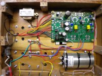
Thanks, I may still mount them on the Board. I guess it will depend on what chassis I choose.short wires should be OK how short I can't say. Resistors 12/13 and 16/26 should be as close to the tube as possible. On my TSE i put all the components I could on the bottom of the board and let the tube sockets mounted to the board come through the top plate.
Sent from my SM-T810 using Tapatalk
It's your call, of course, but for a first build I would advise against using wires to connect the sockets to the board. This would add at least 25 wires (w/o tube rectification) and would greatly increase the chance of future problems. If you are careful and take your time you can get your sockets to be flush with the chassis top.
Attachments
Last edited:
As it turns out I installed the sockets on the Board. Less possible trouble later, and this will be a test bed of sorts, so I can learn. The more stable the better.
OK how about giving me some knowledge about tubes? As I understand it this board is very flexible when it comes to tubes and can be made even more so with the selection of rectifier tubes. Using a different rectifier can give you more or less b+ allowing you to use even more output tubes. Is that correct?
Are there other parts that can be swapped out to dial in the board for even more tubes? I noticed in some builds there are meters and pots included to make things like bias and b+ adjustable or am I wrong? I think I would like to eventually do this but not right away. Any insight into how this is accomplished would be appreciated.
I would like to have some meters in my build any idea where they could be inserted into the circuit?
Sent from my SM-T810 using Tapatalk

The 6L6GC, EL34, 6550, and KT88 are the most common and popular tubes that can be used in this amp with the B+ in the 400 to 450 volt range and a 5K OPT.
There are the KT120 and KT150 tubes that can be used with only a reduced cathode resistor value, but their full potential will not be realized without a lower impedance (3 to 4K) OPT. I have not tried either due to their cost.
The 6V6GT, 6K6GT, and smaller tubes (6F6 and 6G6) could be used, and I do have a 6V6GT SSE triode wired amp which sounds very good, but makes about 2 WPC. It sounds almost as nice as my 45 based TSE for a lot less money. I used the Edcor XSE15-5K OPT and the Allied 6K56VG power transformer for a B+ of about 325 volts. Use a Jumper in place of the 10K resistors feeding the CCS chip on low B+ voltages to avoid starving the CCS. Cathode resistor was 270 ohms I think, I haven't found the amp yet since moving two years ago. I have not tried any of the smaller tubes, although I did plug some 6K6GT's into the 6V6 amp.
There are threads about the KT120, KT150 and 6V6 tubes since other builders have used them. Just about any other pin compatible tube can be made to work in the board by playing with the cathode resistor, the B+ voltage, and the OPT impedance. Since the last two are not easily changed, this is not often done.
Myself and W5JAG have stuffed all sorts of crazy tubes into these amps including sweep tubes and transmitter tubes, but the results vary from smoke and exploding parts to sweet sound. Some of the experiments are scattered throughout this forum. As I have said before, YMMV and you must be prepared to experiment a lot when you deviate from the beaten path.
- Status
- This old topic is closed. If you want to reopen this topic, contact a moderator using the "Report Post" button.
- Home
- More Vendors...
- Tubelab
- SSE first build, need part clarification (help)