Interestingly, connecting G3 to plate increases cathode current considerably.
G3 to ground and G3 to the center tap, are equivalent as far as Ik measures.
I went and got the rest of my 307A, and this is how they match out. First number is Ik with G3 to the center tap; second number is Ik increase when G3 is connected to plate:
39 - 6 ^^^^ above tube that appears to be gassy
42 - 7
43 - 7
42 - 7
44 - 6
60 - 10 -> bypass cap kerblamo
So, as my luck would have it, I randomly picked the gassiest, weakest, tube of the bunch to start with, and for the second tube, picked out the firecracker. It sounded great until the bang, though.
These were all pulls that I got out of the warehouse at Fair Radio for very little money, so four good ones suit me fine.
Fires and exploding parts no longer startle me. I don't know if I should be proud, or ashamed.
Win W5JAG
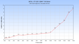
Winner winner chicken dinner - look at this guy.
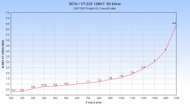
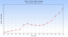
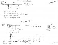
This is the gassy 307A. I actually got better numbers running it up as high as 25 watts, but it showed a tendency to runaway.
I re-ran it with G3 tied to the plate and saw higher IMD numbers, but not by a lot.
307A using the Edcor XSE15-5K.
test conditions:
Ken Rad 39 ma Gasser grey plate, GE 12BH7 grey plate, NU 5W4GT
Triode
G3 tied to cathode
B+ 322
Vk 26
Rk 470 / 25 watt
Ik 55 ma
Pd 16.25
SMPTE IMD 4:1 200Hz:6kHz
Win W5JAG
Attachments

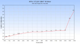
It looks like out of the six tubes, I have one pretty good set, one okay set, one single, and one that is probably bad.
These are all 16 watts Pd, about 55-57 ma cathode current, about 290 volts plate to cathode.
Win W5JAG
These are all 16 watts Pd, about 55-57 ma cathode current, about 290 volts plate to cathode.
Win W5JAG
Attachments
Not that long. Maybe three or four minutes while I double check the set up on the meter. Maybe a bit longer.
When I have some "time" I can try a few and see if or how it changes over time.
I do know that my chinese "6AQ5" (6P1P) push pull amplifier actually shows worse IMD as it heat soaks. I sort of suspect it is the OPT's in that, but they are probably big enough for El34's.
edit: Are you specifically interested in the 307A's, or just in general? I have dismantled the 307A set up to go back to 46/47. I can try it with either when I get the time. It's not hard to set it back up for 307A.
Win W5JAG
Last edited:
What is the upper "safe" voltage limit for 45 / 2A3?
I've set mule 2 up for fixed bias; which is putting 360 ish on the plate. 45 and 2A3 both seem stable, no signs of runaway.
With the cheap Poshan at 7K load, I'm seeing a clean 4 watts with 2A3 and 2 watts with 45 on the scope at 2 KHz. I've cross checked this with several meters including the finger on the load resistor test.
I have a mosfet follower made up, but it doesn't seem to improve power output or distortion, when I sub it into circuit. It seems wired correctly, it's obviously passing signal through it, but I expected the mosfet to get hot. It stays stone cold. I've tried a couple of fet's with the same result.
Win W5JAG
I used to run 45 and 2A3 in the TSE at 275; 320 is probably fine as long as you watch the current. It should make marginally more power that way, and I think Tubelab runs his about 320 or so. Iffy tubes might try to go into run away as you bust spec, though, so keep that in mind.
I can say that if you lose control of the bias, a 45 at 360 volts will arc internally. I got the first arc at about 175 mils; interestingly subsequent arcs took over 200 mils to form - kind of the opposite of what I would expect .....
Also interestingly, it doesn't seem to have hurt the tube at all. I caught it quick the first time, and was on alert after that. Some other parts met their fate, though ....
Win W5JAG
Now that's taken care of. User error. Apparently I've been running both my TSE's using the wrong scale on the voltage meters and pushing the tubes hard. They must be tough because the still work. I have been using the DC voltage scale not the Ma scale. Hum still present on the breadboard using 2a3 but nothing near what it was. Dodged a bullet.
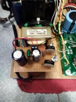
Here is the most recent iteration of Mule 2 - configured for fixed bias.
The board is starting to look pretty sparse at this point - the cathode bypass capacitors are gone, in lieu of grounding the filament transformer center tap, I used a 1/4 watt 10 ohm resistor where the cathode resistor would normally be placed, providing a convenient low voltage point to measure tube current.
Initial plans were to use a nice little Thordarson transformer, 6.3V @ 900 ma; 135V @ 15ma for the 12AT7 filament and bias supply. This was NOS/NIB and I paid a princely $3 for it. Unfortunately, it was bad right out of the box, resisted all attempts to salvage it, and long story short, ultimately went out in fire. This is why you have a kill switch, in my case, the toggle on my variac which I run the Mule from for "testing".
This was a bit of a pisser, since I had planned the layout of the breadboard around the ultimate use of this transformer. Fortunately, a derelict Eico VTVM was located in the warehouse of junk, and it donated it's power transformer to the cause, which actually worked out better from a fit and function standpoint.
The fixed bias board sits on a threaded stud, above the transformer. I just grabbed some parts and free lanced a bias supply, which works fine. Both sides of the perf are used. It uses a full wave solid state rectifier ( to make sure the bias stabilizes before the power tube pulls current ), CRC filter, bleeder, and the voltage dividers. AC into the supply is about 130, and - VDC into the dividers is about 200. On the face of it, this is a bit high, but in practice, it works well, as the Mule B+ is really high with a fixed bias arrangement - almost 360 volts. It takes a LOT of negative bias to deal with this, in excess of - 75 volts.
A lot of rules are being broken here. The B+ is a good 100 volts above the norm and well in excess of spec; the OPT's are 7K. It works well. 2A3 and 45 seem stable. It has no trouble putting out a clean single tone 4 watts with a 2A3 into an 8 ohm load, and 2 watts with a 45. If I am using SE Amp CAD correct, and looking at the load lines correct, the only way it works is due to the 7K load. 8K would be better. At this high voltage, the load lines look better for a 2A3 than a 45. SE Amp CAD suggests more than 6 watts might be obtained with a 2A3 at maximum plate dissipation, provided the front end has the stones. Maybe we'll get to that. I haven't tried 46 or 47 at this scorching B+. Yet.
It's a bit ugly, but it's working well. It still meets the volume criteria that I self imposed. There is room in the bias supply stack for a regulated DC supply for the 12AT7, but that seems somewhat pointless while the power tubes run on AC filaments. I expect this modified SSE would smoke the typical 6SN7/6SL7 => 45/2A3 type amps that are so popular.
edit: one other thing - I'm using 220K resistors in series with the bias supply. Playing around with my bench supply, it didn't seem to want to work with less than about 200K on the grid.
Win W5JAG
Attachments
Last edited:
George, how was the "new" Dayton Hamvention?
MUDDY!
I have been through a Tough Mudder obstacle course race and came out cleaner than when I left the new Dayton.
Thursday (set up day) was fine. There were the typical screw-ups that are bound to happen when something this big is moved (non-existent swap spaces, under sized swap spaces, hot buildings with no AC....) but most were handled better than I expected. Most of the swap spaces were in the infield of a horse trotting track, which was pretty low lying ground. I had a space in higher ground behind the buildings.
Friday there was a big crowd at the open and a good flow of people through the swap meet area. I, and others noted that the sales were far below the usual Dayton norm, and what sold was small items. It was a long walk to the parking area. About 4:30 it began to rain and around 5PM storm warnings were issued on the PA system and the crowd disappeared. I closed up my swap stuff and went walking in the rain. Most other swap vendors had done the same. I went inside the buildings and found them relatively empty as well. I talked to Stan at ESRC, and he also reported light and small sales.
It had rained overnight but the weather was clear and cool (50 degrees) for the open on Saturday. The swap infield was pretty muddy, but traversable even in flip flops before open. There was a large crowd for open (9AM), but a "take shelter immediately" warning came over the PA around 10:30 AM, and the big storm hit. The swap field became a muddy mess, which got worse throughout the day. Most of the swap meet crowd vanished, and did not return. I sold a few small items after lunch, and nothing after 3PM, so I closed up and went shopping.
The swap area was a muddy mess, and I got stuck in the mud trying to walk in flip flops, causing me to lose balance and go splat! I was not the only one. 2WD cars and vans were getting stuck, and the tire spinning made conditions worse, causing more people to pack up and leave. By 4PM I was walking around barefoot and muddy. I think I spent $50 in two hours of shopping, and for the first time that I can remember, left a hamfest without buying a single tube!
I haven't stayed at Dayton for Sunday in maybe 10 years, since Sunday is always bottom feeder day. I left Saturday about 6PM after washing up the best I could in a puddle. Sunday was much worse in the mud department judging by the pictures and videos I have watched. There were cars, vans and even a few pickup trucks being towed out of the mud by a big old John Deere tractor!
If they can solve the mud problems, the new venue isn't too bad. Saturday after the storm passed it got hot and humid. There was talk about one of the buildings being so hot that all the people left, but I didn't have time to go inside Saturday.
There are plenty of videos of the hamfest on Youtube, but most were taken before the mudfest! The usual Japanese guys took videos of their Friday morning walkthrough of the flea market. I and my setup (blue Honda Element) can be found at the 3:32 mark in this one.
https://www.youtube.com/watch?v=rly6tw8S7g8&t=216s
Fires and exploding parts no longer startle me. I don't know if I should be proud, or ashamed.
You should know my opinion on the subject....as long as you are learning something and not destroying rare stuff, it's all good.
PM me when you get a chance. You seem to have more time to blow up stuff than I do right now, maybe I can help!
The only curious result thus far is that 307A, like 47, does not seem to respond well to distributed load.
I noticed the same thing. I got the same power output in UL as I did in triode, but triode sounded so much better. G3 wired to heater-. I didn't try G3 to plate. I did all my testing in a TSE with 5 volts on the heater. I went as far as 400 volts on the plate with 70 mA of current and got about 8 watts with a 5K OPT. I also tried a pair in P-P and got about 30 watts, but I don't remember the exact details. They are buried somewhere in this long thread.
http://www.diyaudio.com/forums/tubes-valves/133034-6l6gc-ab2-amp.html?highlight=6L6GC+AB2
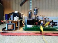
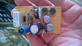
This is a simple screen regulator / bias supply that I built up for my low voltage SSE. It works okay on the bench, have not tried it live, yet.
The voltages in Mule 1 are similar to my low voltage SSE, so I'm going to try it live first in that, and debug it there, before moving it to the SSE.
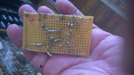
The screen voltage comes from the main B+ supply; bias voltage from a small transformer stripped from a derelict 1980's cheapo clock radio. The board shows a lot of rework - I was aware of the concept of floating stuff above ground, but this is the first time I actually tried it.
It uses a zener shunt "regulator", which initially was all I planned to use, but if I use fixed bias, that would probably set the screens a bit high for tubes like 6Y6, 6W6, and 6U6, so I added an adjustable regulator.
I've tested it at up to 315 volts into the board. It drops out of regulation at 200 volts into the board. It provides an adjustable regulated output from 110 to 160 volts. That may or may not be enough for tubes like 6BQ6 and 6DQ6, but with some rework it can be bumped up, if need be. Topology is a zener shunt, RC low pass filter, TL783 regulator. *IF* it actually works in a live amp, I can give more details when it is finally debugged, if anyone is interested.
Win W5JAG
The voltages in Mule 1 are similar to my low voltage SSE, so I'm going to try it live first in that, and debug it there, before moving it to the SSE.
The screen voltage comes from the main B+ supply; bias voltage from a small transformer stripped from a derelict 1980's cheapo clock radio. The board shows a lot of rework - I was aware of the concept of floating stuff above ground, but this is the first time I actually tried it.
It uses a zener shunt "regulator", which initially was all I planned to use, but if I use fixed bias, that would probably set the screens a bit high for tubes like 6Y6, 6W6, and 6U6, so I added an adjustable regulator.
I've tested it at up to 315 volts into the board. It drops out of regulation at 200 volts into the board. It provides an adjustable regulated output from 110 to 160 volts. That may or may not be enough for tubes like 6BQ6 and 6DQ6, but with some rework it can be bumped up, if need be. Topology is a zener shunt, RC low pass filter, TL783 regulator. *IF* it actually works in a live amp, I can give more details when it is finally debugged, if anyone is interested.
Win W5JAG
Attachments
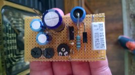
The screen portion of the supply seems to work fine. I jumpered it into Mule 1 last evening, and ran it about four hours feeding the screens of a pair of 6K6 running a constant one watt output into a dummy load. I need to fetch some 6Y6 or 6W6 - they should draw more screen current and represent a better test.
It was uneventful. Voltage into the board was 281 VDC. I set the screens to 150 VDC. The TL783 runs cool to the touch; I was afraid it would need a heatsink, it appears not to thus far. The 10K input resistor does get pretty hot - I measured about 160 F after about three or so hours.
I think there are still some improvements that can be made to it, although it is probably "good enough" as - is.
Win W5JAG
The screen portion of the supply seems to work fine. I jumpered it into Mule 1 last evening, and ran it about four hours feeding the screens of a pair of 6K6 running a constant one watt output into a dummy load. I need to fetch some 6Y6 or 6W6 - they should draw more screen current and represent a better test.
It was uneventful. Voltage into the board was 281 VDC. I set the screens to 150 VDC. The TL783 runs cool to the touch; I was afraid it would need a heatsink, it appears not to thus far. The 10K input resistor does get pretty hot - I measured about 160 F after about three or so hours.
I think there are still some improvements that can be made to it, although it is probably "good enough" as - is.
Win W5JAG
Nice work there W5JAG. Maybe when you get the time can you post a schematic of the screen regulator only with details on the parts and their values ?
As a side question, why do you choose to go with a separate bias supply with transformer ?
Sure, it's as minimalist as it gets right now. Comments, criticisms, and suggestions are welcomed.
I was just going to use a simple zener shunt. I had one 160 volt/ 5 watt zener handy. I allowed for up to 300 volts B+ from my low voltage SSE, so that makes a 140 volt drop. I allowed for 14 ma for the current, so that makes for a 10K ( 140 / .014 = 10000 ) (140*.014 = 1.96 watts) 5 watt input resistor. Power in the zener is 160*.014 + 2.24 watts, so the 5 watt zener looks adequate. The zener has to eat all this when no current is flowing. It is not a coincidence that I happened to have a 10K/5 watt resistor in stock .....
The 1000 ohm / 10 uF capacitor combination is an RC low pass filter, with a cut off about 16 Hz, I think ( can't remember ) to block any noise from the zener. The cap doubles as the input cap for the TL783.
The TL-783 can handle about 1.25 to 125 volts, so the input and output have to accommodate that. I floated it 99 volts above ground, which makes it 100.25 to 224 volts. Since the voltage in is only about 160 or so, that obviously sets the upper limit of output, and the zener string sets the lower. As presently shown, it does about 150 to 110 volts. I used zeners in series here, and fooled with it a bit, and finally decided there was no need to go much lower, and it provides a good safety margin. A 100 ish volt zener is fine here.
I went with a bias supply with transformer to make it easier to adjust tube current. I'll use a separate transformer, because I have one, otherwise you have to use a leg of the high voltage tap, and bleed off a lot of power.
I don't know if it's ready for prime time or not yet. I changed the thumbwheel for a smaller pot so I can place a mounting screw in the middle of the board. I did bring home some 6Y6GA's and tested the whole smack on mule 1. The fixed bias worked fine - maybe a bit too much adjustment, but that can be tweaked. The screen supply held regulation up to about 4 watts output from a pair of 6Y6GA, then it dropped about 10 volts. I haven't done any measurements to find out why, and it still may be okay as - is. Probably that 10K resistor needs to be adjusted to allow more current. I was running the screens at 125 volts, and a 10K load - way, way, too high of a load.
The extra bit of space on the end is for another dc supply for some accessory bits that I haven't built yet ....
Win W5JAG
Attachments
- Status
- This old topic is closed. If you want to reopen this topic, contact a moderator using the "Report Post" button.
- Home
- More Vendors...
- Tubelab
- Tubelab SE: Removing MOSFETs?