The Sharp PQ5EV5 regulator in my TSE failed, and I'm looking to replace it with something that can better handle the higher voltages of a 300B implementation.
Does this part seem like a viable alternative? It is rated for 5V 5A output ("positive fixed" regulator topology) with a dropout voltage of 0.37 and input voltage up to 26v. I'll be using two of these, instead of one, and mounting them to off-board heat-sinks so that there's one per channel.
http://www.digikey.com/product-detail/en/MIC29501-5.0WT/576-2239-ND/1029193
Also the Sharp PQ5EV7 was suggested by craigtone in another thread, the difference from the PQ5EV5 being that it can put out 5V 7.5A, with 45w power dissipation. Seems to be obsolete but can probably find it somewhere.
http://www.digikey.com/product-detail/en/PQ5EV7J0000H/425-2351-5-ND/720290
Any suggestions for other products or values I should be looking for?
Thanks, and happy new year!
Jeff
Last edited:
It might, but it got extremely hot even when they were biased at 72mA when I first got the amp up and running. Adding a second regulator is meant to halve (roughly) the amount of current draw and heat generation on each one.
The PQ5EV5 will probably be fine to use in this application but I wanted to check my options first.
Of course, the path of least resistance would be to convert this TSE into a 45 amp, but it probably wouldn't drive my 91.5 db speakers.
The PQ5EV5 will probably be fine to use in this application but I wanted to check my options first.
Of course, the path of least resistance would be to convert this TSE into a 45 amp, but it probably wouldn't drive my 91.5 db speakers.
That regulator is for the filament supply. Its dissipation is not a function of the bias current. It is a function of the current requirements of the heaters in the tubes you are using. It gets pushed pretty hard for the typical 300B config and any regulator that you replace it with is going to have the same dissipation requirements. The fix is to improve the heatsink.
Sent from my Nexus 6 using Tapatalk
Sent from my Nexus 6 using Tapatalk
I'll have to measure the input voltage on the PQ5EV5 again, but if I recall it might have been around 8V. The datasheet indicates a max input voltage of 7V. If that's the case, then maybe I should lower the value of C1 (currently 15000uf 10V) to bring the input voltage below 7V. Would that help to lower the operating temperature too?
Zman01: I'm glad this has been helpful. We'll get it down!
Zman01: I'm glad this has been helpful. We'll get it down!
I'm using the Weber W022798, which has a 720/660V HV winding, a 6.3V winding, and a 5V winding.
W022798 Transformer

W022798 Transformer
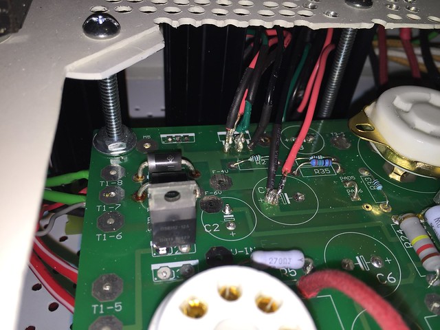
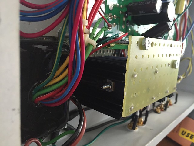
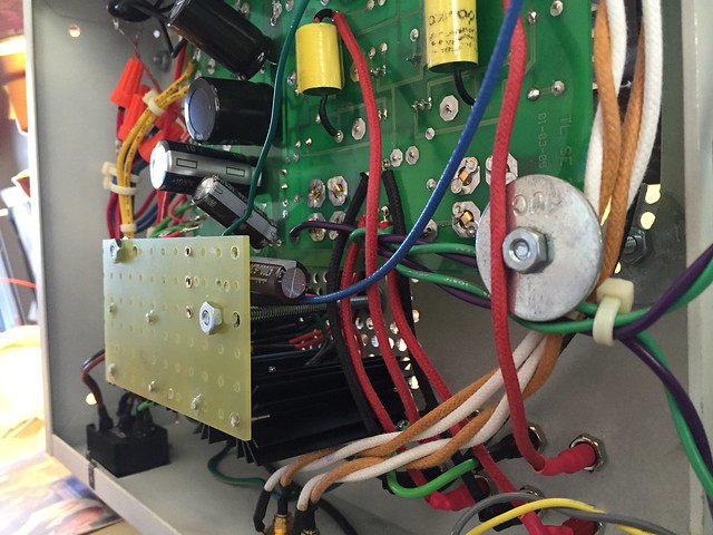
I did the proposed fix by adding a second regulator and it's working very well so far. It uses two new PQ5EV5 regulators along with additional resistors and capacitors to duplicate R1, R2, R35, and C3 in a breakout circuit on a turret board.
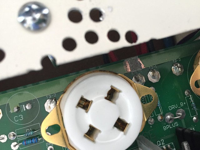
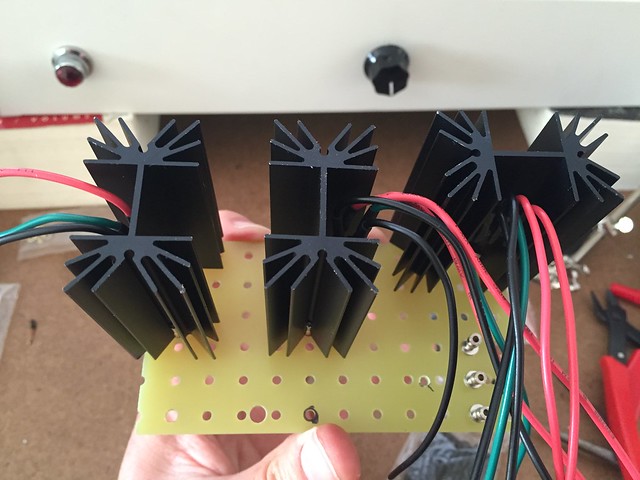
First I removed D1 and U1 from the PCB and then mounted them, along with U1.1, to three 3*C/W TO-220 heatsinks, using mylar strips for insulation. I glued the sinks to a turret board with Loctite Ultragel Control because it can withstand high temperatures and bond a wide variety of material. The turret board is mounted just off the PCB where U1/D1 originally resided. I drilled more vent holes over the turret board to aid in heat dissipation.
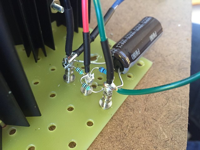
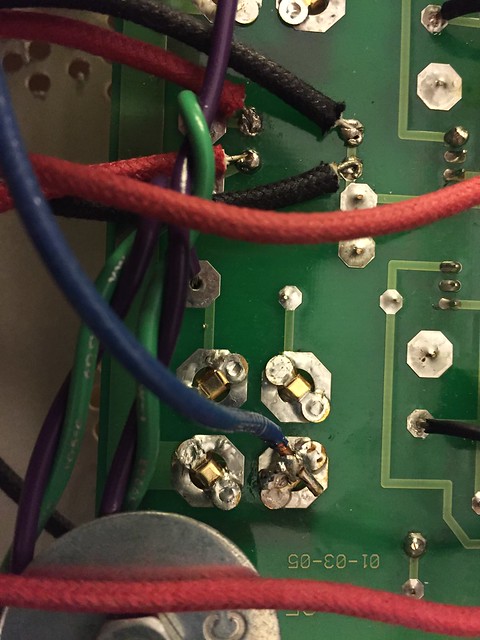
D1 and U1 connect to their original locations on the PCB via 18 AWG solid copper hookup wire from RadioShack soldered to the IC leads. U1.1 uses the same wire to connect pins 1 and 5 to the positive lead of C1, which feeds it, while pins 2, 3, and 4 connect to the R1.1/R2.1/R35.1/C3.1 network wired point-to-point on the turret board. A 14 AWG solid copper THHN wire from Home Depot is soldered from the turret board network to the filament supply of the right channel 300B. U1.1 and the breakout network are grounded by a wire soldered directly to the GND lug on the PCB.
I then cut the trace to the 300B filament supplies at a location between the channels by marking the edges of the cut with an Xacto knife and then scraping the copper trace out with a flathead scredriver. I also put a very hot soldering iron on the exposed trace in order to weaken it and help the process along. The trace from C3 on the PCB goes to the left channel filament, while C3.1 is wired to the right channel filament.
The voltage regulation section seems to run MUCH cooler than it used to, though admittedly it is no longer accessible for measurement with a thermometer.
I have listened for about 10 hours since completing the fix, including two 2+ hour sessions and one that was about 3.5 hours. Aural memory is unreliable, of course, but I think it sounds even better than it did before. This could also be due to further break-in. But it seems to provide slightly more volume and to extract a little more detail from the music. Also it doesn't get bogged down in complex passages like it did before. The amp is in significantly better control of the speakers.
Anyway, it's sounding FANTASTIC and I can't wait to make a phono preamp.
 IMG_3895 by jeffdrouin, on Flickr
 IMG_3867 by jeffdrouin, on Flickr
 IMG_3893 by jeffdrouin, on Flickr
 IMG_3924 by jeffdrouin, on Flickr
 IMG_3927 by jeffdrouin, on Flickr
 IMG_3908 by jeffdrouin, on Flickr
 IMG_3907 by jeffdrouin, on Flickr
First I removed D1 and U1 from the PCB and then mounted them, along with U1.1, to three 3*C/W TO-220 heatsinks, using mylar strips for insulation. I glued the sinks to a turret board with Loctite Ultragel Control because it can withstand high temperatures and bond a wide variety of material. The turret board is mounted just off the PCB where U1/D1 originally resided. I drilled more vent holes over the turret board to aid in heat dissipation.
D1 and U1 connect to their original locations on the PCB via 18 AWG solid copper hookup wire from RadioShack soldered to the IC leads. U1.1 uses the same wire to connect pins 1 and 5 to the positive lead of C1, which feeds it, while pins 2, 3, and 4 connect to the R1.1/R2.1/R35.1/C3.1 network wired point-to-point on the turret board. A 14 AWG solid copper THHN wire from Home Depot is soldered from the turret board network to the filament supply of the right channel 300B. U1.1 and the breakout network are grounded by a wire soldered directly to the GND lug on the PCB.
I then cut the trace to the 300B filament supplies at a location between the channels by marking the edges of the cut with an Xacto knife and then scraping the copper trace out with a flathead scredriver. I also put a very hot soldering iron on the exposed trace in order to weaken it and help the process along. The trace from C3 on the PCB goes to the left channel filament, while C3.1 is wired to the right channel filament.
The voltage regulation section seems to run MUCH cooler than it used to, though admittedly it is no longer accessible for measurement with a thermometer.
I have listened for about 10 hours since completing the fix, including two 2+ hour sessions and one that was about 3.5 hours. Aural memory is unreliable, of course, but I think it sounds even better than it did before. This could also be due to further break-in. But it seems to provide slightly more volume and to extract a little more detail from the music. Also it doesn't get bogged down in complex passages like it did before. The amp is in significantly better control of the speakers.
Anyway, it's sounding FANTASTIC and I can't wait to make a phono preamp.
IMG_3895 by jeffdrouin, on FlickrAn externally hosted image should be here but it was not working when we last tested it.
IMG_3862 by jeffdrouin, on Flickr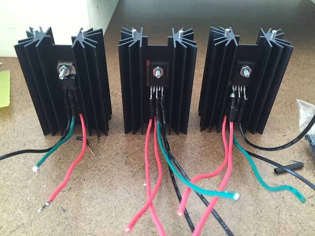 IMG_3867 by jeffdrouin, on Flickr
IMG_3893 by jeffdrouin, on Flickr
IMG_3924 by jeffdrouin, on Flickr
IMG_3927 by jeffdrouin, on Flickr
IMG_3908 by jeffdrouin, on Flickr
IMG_3907 by jeffdrouin, on Flickr
IMG_3867 by jeffdrouin, on Flickr
IMG_3893 by jeffdrouin, on Flickr
IMG_3924 by jeffdrouin, on Flickr
IMG_3927 by jeffdrouin, on Flickr
IMG_3908 by jeffdrouin, on Flickr
IMG_3907 by jeffdrouin, on Flickr
Last edited:
Unfortunately Sharp PQ5EV5 voltage regulator is not available. Could anybody help with alternatives of it? I found MIC29752 - Linear Regulators - Microcontrollers and Processors but I'm not sure could I use it.
I just checked what I used in my recently built 300B and it is a PQ5EV5.
They are still available at digikey:
PQ5EV5J0000H Sharp Microelectronics | Integrated Circuits (ICs) | DigiKey
I've used this heatsink I found on Amazon on the two 300B amps I've built and it works great:
http://a.co/4jYLlVO
Good luck
They are still available at digikey:
PQ5EV5J0000H Sharp Microelectronics | Integrated Circuits (ICs) | DigiKey
I've used this heatsink I found on Amazon on the two 300B amps I've built and it works great:
http://a.co/4jYLlVO
Good luck
- Status
- This old topic is closed. If you want to reopen this topic, contact a moderator using the "Report Post" button.
- Home
- More Vendors...
- Tubelab
- Alternative Voltage Regulator for TSE