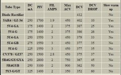
I don't know where I got this from, but given the discussions of late regarding (over) voltages, I thought this table of common rectifier specifications might be useful to the forum.
I have found the voltage drops listed to be a pretty accurate rule of thumb.
A couple of types are left off.
A 5W4 has about the same specs as a 5Y3, but will drop a few more volts.
A 5T4 is a metal 5U4.
A 6087/5Y3WGTB is an indirectly heated verson of the 5Y3.
There are many others.
Win W5JAG
I have found the voltage drops listed to be a pretty accurate rule of thumb.
A couple of types are left off.
A 5W4 has about the same specs as a 5Y3, but will drop a few more volts.
A 5T4 is a metal 5U4.
A 6087/5Y3WGTB is an indirectly heated verson of the 5Y3.
There are many others.
Win W5JAG
Attachments
Last edited:
Rectifier tubes...
A list I copied from somewhere, yesteryear...: (May the real author stand up..)
Five Volt Fullwave Rectifier Tubes:
Tube# - Base - Fvolt - Famp - Vdrop - MaxPmA - MaxPv - notes
5AR4/GZ34-5DA - 5.0 - 1.9 - 17 - 250 - 450 - low Vdrop 5U4/5Y3
5AS4-A - 5T - 5.0 - 3.0 - 50 - 275 - 450 - improved 5U4
5AT4 - 5L - 5.0 - 5.5 - 30 - 800 - 550 - higher power 5U4
5AU4 - 5T - 5.0 - 3.75 - 50 - 325 - 400 - high power 5U4
5AW4 - 5T - 5.0 - 3.7 - 46 - 250 - 450 - long life 5U4
5AX4-GT - 5T - 5.0 - 2.5 - 65 - 175 - 350 - high power 5Y3
5AZ3 - 12BR - 5.0 - 3.0 - 44 - 275 - 600 - compactron 5U4
5AZ4 - 5T* - 5.0 - 2.0 - 60 - 125 - 350 - loctal 5Y3
5BC3 - 9QJ - 5.0 - 3.0 - 53 - 300 - 500 - compactron
5CG4 - 5L - 5.0 - 2.0 - ? - 125 - 400
5DJ4 - 8KS - 5.0 - 3.0 - 44 - 300 - 600 - redesigned 5U4 (higher volts)
5R4-G/GY- 5T - 5.0 - 2.0 - 67 - 250 - 750 - high voltage 5U4
5R4-GYA - 5T - 5.0 - 2.0 - 67 - 250 - 750 - high voltage 5U4 (ruggedized)
5R4-GYB - 5T - 5.0 - 2.0 - 63 - 250 - 900 - high voltage 5U4 (ruggedized)
5T4 - 5T - 5.0 - 2.0 - 45 - 225 - 450 - metal 5U4
5U4-G - 5T - 5.0 - 3.0 - 44 - 225 - 450 - octal 5Z3
5U4-GA - 5T - 5.0 - 3.0 - 44 - 250 - 450
5U4-GB - 5T - 5.0 - 3.0 - 50 - 275 - 450
5V3 - 5T - 5.0 - 3.8 - 47 - 350 - 425 - higher power 5U4
5V3-A - 5T - 5.0 - 3.0 - 42 - 415 - 550 - 5V3 reduced filament current
5V4-G/GA- 5L - 5.0 - 2.0 - 25 - 175 - 375 - octal 83-V
5W4-G/GT- 5T - 5.0 - 1.5 - 45 - 100 - 350 - low power 5Y3
5X4-G - 5Q - 5.0 - 3.0 - 58 - 225 - 450 - 5U4 diff pinout
5X4-GA - 5Q - 5.0 - 3.0 - 47 - 250 - 450
5Y3-G/GT- 5T - 5.0 - 2.0 - 60 - 125 - 350 - octal 80
5Y4-G/GT- 5Q - 5.0 - 2.0 - 60 - 125 - 350 - 5Y3 diff pinout
5Z3 - 5T - 5.0 - 3.0 - 58 - 225 - 450 - 4pin 5U4
5Z4 - 5L - 5.0 - 2.0 - 20 - 125 - 350 - low drop 5Y3
80 - 4C - 5.0 - 2.0 - 60 - 125 - 350 - 4pin 5Y3
83 - 4C - 5.0 - 3.0 - 15 - 225 - 450 - 4pin mercury vapour
83-V - 4C - 5.0 - 2.0 - 25 - 175 - 375 - 4pin 5V4
5931 - 5T - 5.0 - 3.0 - 47 - 300 - 600 - industrial 5U4
6004 - 2AJ - 5.0 - 2.0 - 60 - 120 - 375 - rabbit ear 5U4
6087 - 5L - 5.0 - 2.0 - 50 - 125 - 350
6106 - 5L - 5.0 - 2.0 - 60 - 125 - 350
6853 - 8HE - 5.0 - 1.7 - 60 - 125 - 350
274B ~ 5U4G ~ CV575 ~ 5RGY ~ 5(micro)3C(=russisk 5U4) ~ 5Z3P(=china 5U4)
Six Volt Fullwave Rectifier Tubes
Tube# - Base - Fvolt - Famp - Vdrop - MaxPmA - MaxPv
6AX6-G - 7Q - 6.3 - 2.5 - 21 - 250 - 350
6BW4 - 9DJ - 6.3 - 0.9 - 40 - 100 - 325
6BY5-G/GA-6CN - 6.3 - 1.6 - 32 - 175 - 375
6CA4 - 9M - 6.3 - 1.0 - ? - 150 - ?
6W5-G - 6S - 6.3 - 0.9 - 24 - 90 - 325
6X4 - 5BS - 6.3 - 0.6 - 22 - 90 - 360
6X5 - 6S - 6.3 - 0.6 - 22 - 80 - 360
6Z5 - 6K - 6.3 - 0.8* - ? - 60 - ?
6ZY5-G - 6S - 6.3 - 0.3 - 18 - 40 - 325
7Y4 - 5AB - 6.3 - 0.5 - 22 - 70 - 325
7Z4 - 5AB - 6.3 - 0.9 - 40 - 100 - 325
84/6Z4 - 4C - 6.3 - 0.3 - 20 - 60 - 325
5993 - 5993 - 6.3 - 0.8 - ? - 60 - 260
5852 - 6S - 6.3 - 1.2 - ? - 65 - 300
6202 - 5BS - 6.3 - 0.6 - 22 - 55 - 325
6203 - 9CD - 6.3 - 0.9 - 22 - 77 - 325
6325 - 6325 - 6.3 - 2.7 - ? - 250 - 780
6754 - 9ET - 6.3 - 1.0 - ? - 90 - 325
Misc Volt Fullwave Rectifier Tubes
Tube# - Base - Fvolt - Famp - Vdrop - MaxPmA - MaxPv
0Z4 - 4R - none - none - ? - 110 - 880
82 - 4C - 2.5 - 3.0 - 15 - 115 - 450
3DG4 - 5DE - 3.3 - 3.8 - 32 - 400 - 325
12BW4 - 9DJ - 12.6 - 0.45 - 40 - 100 - 325
12DF5 - 9BS - 12.6 - 0.45 - 40 - 100 - 350
12X4 - 5BS - 12.6 - 0.3 - 22 - 90 - 360
25X6 - 7Q - 25.0 - 0.3 - 25 - 60 - 125
25Y5 - 6E - 25.0 - 0.3 - ? - 42 - 250
25Z5 - 6E - 25.0 - 0.3 - 22 - 75 - 235
25Z6 - 7Q - 25.0 - 0.3 - 22 - 75 - 235
26Z5 - 9BS - 26.5 - 0.2 - 22 - 50 - 325
28Z5 - 6BJ - 28.0 - 0.24 - 40 - 100 - 325
50AX6-G - 7Q - 50.0 - 0.3 - 21 - 250 - 350
50X6 - 7AJ - 50.0 - 0.15 - 22 - 75 - 235
50Y6 - 7Q - 50.0 - 0.15 - 22 - 75 - 235
50Y7 - 8AN - 50.0 - 0.15 - 22 - 75 - 235
50Z6 - 7B - 50.0 - 0.3 - ? - 75 - 235
50Z7 - 8AN - 50.0 - 0.15 - 21 - 65 - 235
117Z6 - 7Q - 117 - 0.075 - 15.5 - 60 - 235
5690 - 5690 - 12.6* - 1.2 - 17 - 125 - 350
5U4 Compatible Fullwave Rectifier Tubes
Tube# - Base - Fvolt - Famp - Vdrop - MaxPmA - MaxPv - notes
5AR4/GZ34-5DA* - 5.0 - 1.9 - 17 - 250 - 450 - low Vdrop 5U4/5Y3
5AS4-A - 5T - 5.0 - 3.0 - 50 - 275 - 450 - improved 5U4
5AU4 - 5T - 5.0 - 3.75*- 50 - 325 - 400 - high power 5U4
5AW4 - 5T - 5.0 - 3.7* - 46 - 250 - 450 - long life 5U4
5DJ4 - 8KS* - 5.0 - 3.0 - 44 - 300 - 600 - redesigned 5U4 (higher volts)
5R4-G/GY- 5T - 5.0 - 2.0 - 67 - 250 - 750 - ruggedized 5U4 (higher volts)
5R4-GYA - 5T - 5.0 - 2.0 - 67 - 250 - 750
5R4-GYB - 5T - 5.0 - 2.0 - 63 - 250 - 900
5T4 - 5T - 5.0 - 2.0 - 45 - 225 - 450 - metal 5U4
5U4-G - 5T - 5.0 - 3.0 - 44 - 225 - 450 - octal 5Z3
5U4-GA - 5T - 5.0 - 3.0 - 44 - 250 - 450
5U4-GB - 5T - 5.0 - 3.0 - 50 - 275 - 450
5V3 - 5T - 5.0 - 3.8* - 47 - 350 - 425 - higher power 5U4
5V3-A - 5T - 5.0 - 3.0 - 42 - 415 - 550 - 5V3 reduced filament current
5931 - 5T - 5.0 - 3.0 - 47 - 300 - 600 - industrial 5U4
*Extra connections on base - may not be plug-in compatible in some circuits.
*Higher heater current requirement - may not work in many 5U4 circuits.
5Y3 Compatible Fullwave Rectifier Tubes
Tube# - Base - Fvolt - Famp - Vdrop - MaxPmA - MaxPv - notes
5AR4/GZ34-5DA* - 5.0 - 1.9 - 17 - 250 - 450 - low Vdrop 5U4/5Y3
5AX4-GT - 5T - 5.0 - 2.5* - 65 - 175 - 350 - high power 5Y3
5CG4 - 5L* - 5.0 - 2.0 - ? - 125 - 400
5R4-G/GY- 5T - 5.0 - 2.0 - 67 - 250 - 750 - ruggedized 5U4 (higher volts)
5R4-GYA - 5T - 5.0 - 2.0 - 67 - 250 - 750
5R4-GYB - 5T - 5.0 - 2.0 - 63 - 250 - 900
5T4 - 5T - 5.0 - 2.0 - 45 - 225 - 450 - metal 5U4
5V4-G/GA- 5L* - 5.0 - 2.0 - 25 - 175 - 375 - octal 83-V
5W4-G/GT- 5T - 5.0 - 1.5 - 45 - 100 - 350 - low power 5Y3
5Y3-G/GT- 5T - 5.0 - 2.0 - 60 - 125 - 350 - octal 80
5Z4 - 5L* - 5.0 - 2.0 - 20 - 125 - 350 - low drop 5Y3
6087 - 5L* - 5.0 - 2.0 - 50 - 125 - 350 - special 5Y3
6106 - 5L* - 5.0 - 2.0 - 60 - 125 - 350 - special 5Y3
6853 - 8HE* - 5.0 - 1.7 - 60 - 125 - 350
*Extra connections on base - may not be plug-in compatible in some circuits.
*Higher heater current requirement - may not work in many 5Y3 circuits.
Four Pin Fullwave Rectifier Tubes
Tube# - Base - Fvolt - Famp - Vdrop - MaxPmA - MaxPv - notes
5Z3 - 4C - 5.0 - 3.0 - 58 - 225 - 450 - 4pin 5U4
80 - 4C - 5.0 - 2.0 - 60 - 125 - 350 - 4pin 5Y3
83 - 4C - 5.0 - 3.0 - 15 - 225 - 450 - 4pin mercury vapour
83-V - 4C - 5.0 - 2.0 - 25 - 175 - 375 - 4pin 5V4
--------
Arne K
rectifiers
Additional info:
Why use a different rectifier tube?
Normally the best replacement tube is to use the same type tube number as
originally designed for the circuit. These days it is sometimes the case
that the original tube is not available, hard to find, or very expensive.
Many times substitutions can be used that may be more readily available,
or lower cost, yet still perform in the circuit as well as the originally
designated tube type.
There are two basic fullwave power rectifier tubes that you will likely
encounter. The 5Y3 family, and the 5U4 family. The 5Y3 family is the
oldest fullwave rectifier design. The 5Y3 design goes all the way back
to the 1920s (type 80 tube) and is still being made today. The original
design was the type 80 tube. When the octal base format came into use,
the type 80 tube had an octal base put on it and the type became the
5Y3. You can swap between the tubes using a base adapter.
The orignal type 80 tube came in a globe/balloon style. Later the type 80
was switched to the ST shape which is more rugged because it supports the
internal elements. Long after the end of design life for the type 80 tube,
it was made available in the GT style for replacement use. This was really
just a 5Y3GT with a four pin base.
When the 5Y3 came out, all they did was to put an octal base on the type 80
tube. At this time, the type 80 tubes were using the ST shaped glass, so
the first 5Y3 tubes, which were called 5Y3G, also used the ST shape.
Later on as equipment manufacturers demanded smaller tubes, the 5Y3 was
packed into the smaller GT style. Beyond that, the design remains
largely the same as when the type 80 tube was first introduced.
Origonally if more power than the type 80 tube could provide was needed,
you needed to design in two or more tubes. The main reason for requiring
two tubes was that the heat disipation for a fullwave rectifier of that
power would be too much to handle in the standard size tube.
To deal with this, the type 83 tube was designed.
The type 83 tube uses mercury vapour (the same gas in florescent lights)
to reduce the internal resistance. Doing so reduces the amount of power
disipated by the tube and thus the heat generated. This allows a high power
fullwave rectifier to be placed in the same package as the original
type 80 tube.
The down side to this is that the mercury creates its own set of problems.
The toxic aspects of mercury were not considered to be as big an issue
at that time as it is now. However there are other problems. The primary
problem is that mercury is a liquid at room temperature. That causes it
to condense onto the internal tube elements. If voltage is applied to the
plates before the heater has warmed up the tube (and turn the mercury into
gas), the mercury can cause internal shorting or arcing to occur. This can
cause damage to the tube and to the circuits in which it is used.
Note: there is a tube type called 83-V. It is unfortunate that they
selected the "83" number for it as it is rather different than a type 83
tube. It is closer to a type 80 tube but with a reduced internal resistance.
The reduced resistance is achieved by placing the cathode/heater and
plate closer together. This makes it much harder to manufacture and
more suceptable to shorting out. A shorted power rectifier tube can cause
a lot of damage to the circuits in which it is used.
There were various attempts made to deal with the mercury problem in the
type 83 tube. One solution was the 5Z3 tube. The 5Z3 tube uses a larger
glass bulb and larger plates to handle the higher power. It also has a
bigger heater so that it can emit more electrons that are required for
the higher power levels. The end result is a tube with twice the plate
current as a type 80 or 5Y3 tube and slightly more plate voltage.
For high power amplifiers, radios and TVs, this was just what was needed.
The 5Z3 uses the same base and pin out as the type 80 tube, so it is
actually possible to put a 5Z3 in a type 80 socket. Normally this should
be avoided though, the 5Z3 uses a 3amp heater whereas a type 80 tube uses
a 2amp heater. Putting a 5Z3 in a 5Y3 circuit will likely cause the power
transformer to overheat and fail.
Like the type 80, when the octal socket came into use, the 5Z3 had an
octal base put on it and it became the 5U4. The "G" style 5U4 is the
original 5Z3 ST shaped tube using an octal base. Also like the 5Y3,
the tube was reduced in size by using a GT bulb. The 5U4GT bulb is
much larger than the 5Y3GT bulb to accommodate the larger 5U4 plates.
There are two basic 5U4GT tubes. The 5U4GA and the 5U4GB. The GA is
simply the old 5U4G crammed into a smaller GT bulb. The GB is a GA
with an improved design (slightly more power output).
Originally the 5U4GB design was called the 5AS4 (ST version) and later the
5AS4A (GT version). Due to lack of sales and multiple inventory issues
for a tube that was essentially the same as the 5U4, manufacturers decided
to name it the 5U4GB and retire the 5U4, 5U4GA and 5AS4 tubes.
You will often see tubes labeled 5U4GA/GB or 5U4GB/5AS4A indicating
that they are intended for replacement of those tube types.
For new designs the differences are not normally a problem, and for most
radio and TV designs the differences are minor enough to not make a
difference. For some audio amplifiers the slight differences in design
can result in a shift of voltages enough to make a noticable difference
in the way the amplifier sounds. In a properly designed amplifier
the different tubes should not cause damage to the amplifier. Switching
between the various types can be a way to tweak the amplifier for a
different sound. The general rule of thumb is that a tube with more
voltage drop will make the amplifier sound more mellow and one with
less voltage drop will sound more firm. However the nature of the beast
is that the actual results will depend heavily on the amplifier design
and the other tubes used in the amplifier.
Another aspect is that a used tube can make a difference in the sound of
an amplifier. As a tube ages, the number of electrons emited from the
cathode is reduced. This has the effect of increasing the voltage drop
across the tube. The result is that an old amplifer with well used tubes
can sound more mellow than a new amplifier of the same design.
Over the years other tubes have been designed that take their history
from the original type 80 and type 5Z3 tubes. Some were designed to have
lower voltage drop, others to have more maximum plate current and or
voltage.
One of the more popular replacement versions is the 5T4 which is a metal
version of the 5U4/5Y3 tube. Because it uses a 2 amp heater but has the
voltage and current rating of a 5U4, the 5T4 can be used in place of
either a 5U4 or a 5Y3 in most circuits. The 5T4 tube is no longer made,
but there are still a lot of them available as the military used them
extensively. Because of the metal envelope, the tube is very rugged.
The main problem is that since it is metal, you cannot see inside
the tube to see if it is gassy, arcing or the heater is not working.
Another popular replacement version with a 2amp heater that allows it
to be used in either 5U4 or 5Y3 circuits is the 5R4 tube. The 5R4 also
has a significantly higher plate voltage and a low loss base. The GYA
and GYB versions are highly ruggedized for aircraft use. The main
problem is that the higher plate voltage also means a higher voltage
drop across the tube. Also the GYA and GYB verisons have large heavy
bases as a part of the ruggedization.
A popular tube still being made is the 5AR4/GZ34. This is basically
an improved redesigned 5U4/5Y3 tube. It has a 1.9amp heater and plate
voltage and current similar to the 5U4 so it can be used in either
circuit. However it has a much lower voltage drop so care should
be used to be sure that the circuit can handle the extra current
surge. This tube is usually best used in a circuit that is designed
to handle the low voltage drop. The other potential problem with
this tube is that it has an internal connection on pin 1 which can
potentially cause problems with some circuits. Don't use this tube
unless you know that the circuit can handle it.
Another popular redesigned tube that is still in production is the
5DJ4. This tube is essentially a 5U4 with higher plate voltage and
current. It also has extra connections on the base which can be a
potential problem. Like the 5AR4, don't use this tube unless you
know that the circuit can handle it. Serious damage can potentially
occur in some circuits.
If you need the higher voltage or current of the 5DJ4 but the extra
connections on the base are a problem, consider the 5831. The 5831
has similar characteristics but with the standard 5U4 pinout.
Generally you should stay away from the 5AU4 or 5AW4 tubes as
replacements for a 5U4. These tubes have 20% higher filament
current which can cause the power transformer to overheat if it
is not designed to take the extra load. If you know that the
transformer can handle the extra current, then you can use them.
The 5AU4 is designed to have more current output and the 5AW4
is designed to have a longer life. Unless you have a specific need
for one of these tubes, you should consider one of the other tubes
as a substitute. Neither of these tubes is being made anymore.
The 5V3 is another one of the troublesome tube numbers. There are
two versions of the tube, the 5V3 and the 5V3A. The 5V3 should be
avoided as a 5U4 replacement because it has a 20% higher heater
current which can potentially damage the power transformer.
The 5V3A has the same heater current as the 5U4 and can be safely
used as a substitute. The main advantage of the 5V3 is that it
has a higher plate current and voltage. so it can be used in
more demanding circuits (or last longer in undemanding circuits).
However given the serious difference between the 5V3 and 5V3A
types, extreme care must be used that you don't accidently put
the wrong tube in a circuit that cannot handle it.
For circuits that use a 5Y3, there are a few more options
available for substitution.
For low voltage drop, as well as the 5AR4, there are the 5V4 and 5Z4
tubes. The 5V4 tube comes in the older ST style "G" glass and in the
newer "GT" style glass. The 5V4 is an octal version of the four pin
83-V tube. The 5Z4 also comes in the ST and GT styles, but has
slightly lower voltage drop (20v vs 25v). These tubes don't have
quite as much plate voltage as the 5AR4, but will work in a circuit
designed for the 5Y3 as long as the lower voltage drop is not a
problem. The 5CG4 is rare, but is essentially a 5V4 type tube in a small
GT package.
The 5W4 tube is a lower power version of the 5Y3. It uses less power
so it runs cooler and lasts longer, but it may not work in all circuits
due to the lower plate current rating.
There are also three special industrial/military versions of the 5Y3.
The 6087 is the same as the 5Y3 but is in a low loss base and rugged
construction for mobile and aircraft use.
The 6106 is a highly specialized version of the 5Y3 tube.
It is a Bendix Red Bank tube. These tubes where designed for the
military to withstand the most punishment that could be thrown at a
tube. These are the best 5Y3 tubes ever made.
The 6853 is an industrial version of the 5Y3. It has a lower filament
current so that it lasts longer. The rest of the characteristics are
the same as a normal 5Y3.
How to decide if you can use a different tube type.
The commonly used replacement tubes for the 5U4 and 5Y3 tubes
are listed in the 5U4/5Y3 Compatible Fullwave Rectifier Tubes
tables above.
The first thing to check is the filament voltage and current.
The replacement tube should have the same filament voltage.
The filament current should be equal to or less than the original design.
Lower filament current usually means the tube is not able to handle the
same power levels as the original design, but not always. The plate
characteristics need to be checked to see if it will work.
Higher filament currents should be avoided as they can cause the power
transformer to overheat and fail unless it is designed to handle the
higher current requirement.
The next thing to check is the maximum plate voltage. The maximum plate
voltage should be at least as high as the tube you are replacing.
If you know the maximum voltage that will be encountered is less than
the tube rating, you may be able to use a lower rated tube, but care
must be used as the tube will arc internally causing potential circuit
damage if the plate voltage rating is exceeded.
Next you will want to check the maximum plate current capability.
Like the plate voltage rating, the maximum plate current rating should
be equal to or greater than the tube being replaced. With plate current
there is greater flexability as often the maximum rating of the tube is
seldom reached. You may be able to get away with a lower rated tube.
The problem that can be encountered here is the tube may be over driven
causing shorter life for the tube and possible power supply collapse.
Usually this isn't as damaging as when the tube experiences internal
arcing, but in some circuits it may potentially be a problem. If you
are not sure, always go with equal to or better current rating for
the plates.
Finally, look at the tube voltage drop. This is normally a characteristic
that is not as much a problem. In radios and TVs it often has little or
no impact as they are typically designed to handle the varience.
In amplifiers, it can affect how the amplifier sounds. Especially
amplifiers that used fixed bias and little or no inverse feedback.
When considering the voltage drop, keep in mind that the rated voltage
drop is normally given for the maximum voltage and current rating for
the plate. The actual voltage drop in use will depend on the current
flow through the plate and the voltage applied. The voltage drop
for a given voltage and current will also depend on the construction
of the tube. Some tubes will have a higher variablity of the voltage
drop as the current changes and others will have less of a change.
Generally a tube with a lower voltage drop to start will have less
of a change in the voltage drop with a change in the plate current.
A well used tube will generally exhibit a larger change in voltage drop
with a change in the plate current.
One of the characteristics of a gas rectifier (such as a mercury
rectifier) is that they tend to exhibit less of a change in the voltage
drop. Mercury vapour tubes are very stable in this regard (which is
the primary reason that Hickok used the type 83 tube in their tube
tester). Neon, Xeon, and Argon are other gases that are popular to use
in gas rectifiers.
The purpose of the gas is to provide a plasma inside the tube which
reduces the internal resistance during operation. This characteristic
comes with a price though. The gas will not ionize (turn into plasma)
until a relatively high voltage is developed across the tube. This is
typically between 50 volts and 150 volts. The exact voltage at which
the ionization starts is dependant upon a number of factors, including
temperature of the tube, the type and amount of gas used, and the
internal construction of the tube (distance between the plate and
cathode). Once the ionization occurs the tube resistance drops rapidly
(within microseconds). This causes a strong current surge which can
disrupt or harm the circuits if they are not designed to handle this
situation.
Solid State Fullwave Rectifier Tube Replacements
An alternative to using a vacuum tube replacement is to use a solid
state tube replacement. Most of the replacements available use a pair
of silicon diodes to replace the vacuum tube rectifier elements.
The silicon rectifier has several big advantages. One is that they
will normally last for the life of the device they are used in.
Also since they don't require a heater to boil electrons off the
cathode material, they use far less power and don't generate the
heat like vacuum tube rectifier.
They do have one disadvantage though, they have very little internal
resistance. This can potentially cause trouble in some vacuum tube
circuits. The low resistance can cause higher surge currents in the
rectifier circuit which can shorten the life of electrolytic capacitors.
it can also cause an increase in hum bleed-thru since the internal
resistance of the vacuum tube rectifier is normally included as a part
of the power supply filtering in a tube circuit.
Some solid state tube rectifier replacements account for this by
including a resistor in the circuit to emulate the internal resistance
of the original tube. However the resistor is an added source of heat
and makes the replacement more expensive to make, so most do not include
the resistor.
If the circuit can handle the solid state rectifier, it can provide
more power because of the reduced power loss compared to a vaccum tube.
If you can handle a soldering iron, it is easy to make a solid state
5Y3 or 5U4 tube replacement. First get an octal plug. This can be bought
from a tube supplier, or can be obtained by removing one from a dead tube.
Next you will need two 1N4007 diodes. These are available from most
electronics suppliers. Just about any diode with a current rating of
at least one amp and a voltage of 1000V or higher will work.
Note: Diodes require higher ratings than tubes because they are not as
forgiving as tubes. A tube can normally withstand a momentary event
that exceeds it's rating without permanent damage. Solid state diodes
cannot, they will fail immediately. Because of that, the diode rating
needs to be selected such that it will never be possible for it to
be exceeded. The general rule of thumb is to use at least double the
voltage and current rating as the design calls for.
To construct the rectifier tube replacement, connect the anode of
one diode to pin 4 and the cathode to pin 8. Connect the anode of the
other diode to pin 6 and the cathode also to pin 8.
For a four pin rectifier, connect one diode anode to pin 2 and the
other diode anode to pin 3. Connect the cathodes of the diodes to pin 4.
Congradulations, you now have a solid state tube replacement.
However, you aren't done yet.
As was noted above, solid state rectifier tube replacements have much
lower internal resistance compared to vacuum tube rectifiers. This
can cause problems and potentially even damage to the circuits if they
are not designed to handle this difference.
There are two ways to fix this. One is to modify the circuit by placing
a resistor in series with the plate supply transformer center tap and
ground. The other way you can fix this is by adding the resistor in
series with the cathodes of the diodes and pin 8 (pin 4 on 4pin tubes).
The advantage of placing the resistor in the solid state rectifier tube
replacement is that you are not modifying the circuit so that you can
easily plug a regular vacuum tube in the circuit again without removing
the added resistor from the circuit. The disadvantage of placing the
resistor in the solid state rectifier tube replacement is that the
resistor will get hot and will have dangerous voltages on it.
It is strongly recommended that you properly insulate the solid state
rectifier tube replacement so that you do not accidently touch the
exposed lethal voltages on the connections.
Design note: The recommended design for 5U4 and 5Y3 tubes is to take
power off pin 8 of the filament. A few designs take the power from
pin 2. This may result in increased hum because of the filament voltage
getting into the DC power. To fix this, you can either rewire the
circuit to take power from pin 8, or move the cathodes of the diodes
in the solid state tube replacement to pin 2. Do not short pins 2
and 8 as this will short out the heater supply and damage the circuits.
For the four pin rectifiers, the wiring is even less consistent than
with the octal circuits. You may need to move the cathodes to pin 1
instead of pin 4. As with the octal tube replacement, do not short
pins 1 and 4 or you will damage the circuits.
While in some cases you may be able to get away without using the
resistor, in others it may be wise to use it to prevent damage to
the circuits or change in the characteristics of the circuit.
The chart below provides some suggested values to use.
As with all things like this, these are only suggested values.
The actual ideal values will be specific to the circuit and use.
Selecting the resistor for the solid state rectifier tube replacement.
5AR4 - 20 ohms 10 watts
5AS4 - 20 ohms 10 watts
5AU4 - 30 ohms 10 watts
5AW4 - 150 ohms 10 watts
5AX4 - 47 ohms 2 watts
5DJ4 - 100 ohms 10 watts
5T4 - 150 ohms 10 watts
5U4G/GA - 150 ohms 10 watts
5U4GB - 20 ohms 10 watts
5V4(all) - 100 ohms 5 watts
5W4(all) - 47 ohms 2 watts
5Y3(all) - 47 ohms 2 watts
5Z4 - 47 ohms 2 watts
80 - 47 ohms 2 watts
83 - 10 ohms 2 watts
83V - 47 ohms 2 watts
5Z3 - 150 ohms 10 watts
Note: replacement of the 5R4 with a solid state tube replacement is
not recommended without careful review of the circuit in which it
is used. If the 5R4 is being used in a circuit where the 5U4 would
normally be installed, use the 5U4 resistor.
Note: Silicon rectifier diodes have a typical voltage drop of between
0.5volt and 1.0volt. This can be averaged to 0.75volts for the math.
Divide this by the current flow to get the effective resistance.
Thus for a 250mA tube circuit you would get 0.75 / 0.25 = 3 ohms.
This is much lower than the 44 ohms of a normal 5U4 tube.
Another way to determine the resistor is to install a new tube
in the circuit and set it up to use the maximum amount of power it
would normally use. Measure the voltage between ground and the power
take-off pin (typically pin 8 for octal, pin 4 for 4pin types).
Mark this voltage down as a reference.
Note: these voltages don't have to be super accurate. A 5% tolerance
for this type of work is more than adequate. Most tube circuits are
designed to handle tolerances of 10% to 20% or even more.
Remove the rectifier tube and install the solid state tube replacement
using a variable resistor with the appropriate wattage for the
resistor. Set the resistor value to the value listed in the table.
Again apply power and set up the circuit for the maximum normal load.
While measuring the power takeoff voltage, adjust the resistor to
achieve the same voltage as obtained with the new tube. Turn off
the power, remove the variable resistor from the circuit and measure
the resistance of the variable resistor for that obtained setting
(be sure not to disturb the setting). This is the value of resistor
that should be used with the circuit. (You can use the next closest
standard resistance value available.) The wattage is determined by
multiplying the square of the maximum current in amps times the
resistance. Then use the next higher wattage resistor.
Thus for a 5U4 circuit rated at 225mA using a 150 ohm resistor;
0.225*0.225*150=7.6watts. For this you would use a 10watt resistor.
Generally try to pick a wattage 20% to 50% higher to prevent the
resistor from overheating and burning up.
Do not use a resistor with less wattage or it will overheat.
Do not use a resistor with too high of a wattage either. A part of
the purpose of the resistor is to act as a safety valve in case the
diodes short out. The resistor should burn out before the shorted
diode destroys the rest of the circuits.
Always be sure to provide adequate ventalation for power resistors
so that the heat can escape. Also keep them away from other parts
that can be damaged by the heat.
Unfortunately, where the normal failure for a tube is to fail open,
the normal failure for a solid state diode is to short out.
This can potentially cause nasty damage to the circuits.
Warning: Use extreme caution when working with tube circuits.
Do not do this work if you are not qualified to do it.
The voltages in tube circuits are lethal and can kill you.
<eof>
-------------
Arne K
")
5W4-G/GT- 5T - 5.0 - 1.5 - 45 - 100 - 350 - low power 5Y3.
The Tung Sol datasheet for the 5W4GT rectifier does indicate a voltage drop of 45V but when I use a
GE 5W4GT in my SSE I find the drop is about 5V lower than either the 5Y3GT or 6087 rectifiers in the
same SSE. In this specific case the drop appears to be much greater than 45V.
The Tung Sol datasheet for the 5W4GT rectifier does indicate a voltage drop of 45V but when I use a
GE 5W4GT in my SSE I find the drop is about 5V lower than either the 5Y3GT or 6087 rectifiers in the
same SSE. In this specific case the drop appears to be much greater than 45V.
Someone went to a lot of trouble to compile that list, so it pains me to say this, but, looking it over, I also think some of the listed voltage drops are inaccurate.
For example, look at the 6X5 and the 5852. The voltage drop for 6X5 is listed as 22 volts. 5852 is the Bendix Red Bank 6X5 (sometimes found, incorrectly, labeled as a 6AX5) where no drop is listed. 60 volts is an reasonably accurate rule of thumb for 6X5, 6AX5, and 5852 types - similar to a 5Y3 type .....
The 5R4 type, 5U4 type, and 5W4 drops look wrong to me as well. I think the chart in post one is a reasonably accurate rule of thumb based on my experience.
It was certainly interesting to see all the different rectifier types - I see a few types I was unaware of that I will start looking for at hamfests.
Thank you, Arne.
Win W5JAG
edit: the "y" contained in a suffix, AFAIK, indicates a micanol base. The micanol base may, or may not, be attached to a ruggedized tube. A 5R4 GY is not a ruggedized 5R4 - it is a 5R4 in a shoulder bottle, with a micanol base. The ruggedized 5R4 is the high altitude potato masher types - the exact suffix escapes me at the moment ....
Last edited:
.... The voltage drop for 6X5 is listed as 22 volts. 5852 is the Bendix Red Bank 6X5 (sometimes found, incorrectly, labeled as a 6AX5) where no drop is listed. 60 volts is an reasonably accurate rule of thumb for 6X5 ....
Nope, I was wrong, playing around with some, the voltage drop for 6X5 and 5852 is 22 volts.
Win W5JAG
I hope this helps:
Rectifier Review-Comparison
Dubstep Girl's Massive 5AR4/5R4/5U4G Rectifier Review/Comparison! (Rectifer Tube Rolling thread)
5R4 / 5R4GY Tube Rectifiers - A Mini Shoot-out - Lord Soth - Tubes Asylum
Rectifier Review-Comparison
Dubstep Girl's Massive 5AR4/5R4/5U4G Rectifier Review/Comparison! (Rectifer Tube Rolling thread)
5R4 / 5R4GY Tube Rectifiers - A Mini Shoot-out - Lord Soth - Tubes Asylum
Ditto here from a new guy.@Cobra2...
I just wanted to thank-you for taking the time...
To post your contributions about Tube 'Rectifiers' to this Thread.
Greatly appreciated! Regards,
-Tim.
__________
I'm researching rectifiers now for a project I've just started so thanks for bumping this thread up, Tim. It's good info.
One thing to consider for rectifiers is some will slowly ramp up B+, and some will turn on B+ really quickly. Indirectly heated are slow ramp up, and slow ramp up is better for DHT tube life.
5AR4/GZ34 can provide enough current to power most any DHT, and are slow ramp.
There are other options that have more voltage drop if you need lower B+.
5AR4/GZ34 can provide enough current to power most any DHT, and are slow ramp.
There are other options that have more voltage drop if you need lower B+.
- Home
- More Vendors...
- Tubelab
- A handy table of common Rectifier specifications