Finally started my TSE build tonight and thought I would document it and ask questions here. I soldered in R1-R7.
When soldering R7, some of the solder might have flowed onto the adjacent pad for R6, but I can't really tell. It could just be some flux in there (or it could be nothing). If I read the schematic right, R6 and R7 are actually connected at this point.
Anything to worry about? Should I try to clean it out?
Here's a closeup image.
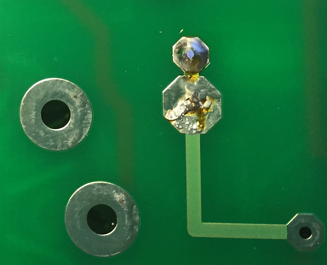 r6-r7-cropped by jeffdrouin, on Flickr
Not my cleanest work.
When soldering R7, some of the solder might have flowed onto the adjacent pad for R6, but I can't really tell. It could just be some flux in there (or it could be nothing). If I read the schematic right, R6 and R7 are actually connected at this point.
Anything to worry about? Should I try to clean it out?
Here's a closeup image.
r6-r7-cropped by jeffdrouin, on FlickrNot my cleanest work.
Thanks for confirming, Bill.
I finished soldering the resistors and have begun on the tube sockets, starting with the octal. Some of the gaps in the pads were so large that it was difficult to fill the entire hole with solder, else I'd have to use an excessive amount and it would start running toward the socket. So, I soldered at the side with the smallest gap. It feels like a *very* secure joint and I don't think I need to fill them.
Is that OK, or should I try to fill the entire hole?
Here's what they look like:
 socket-solder by jeffdrouin, on Flickr
I finished soldering the resistors and have begun on the tube sockets, starting with the octal. Some of the gaps in the pads were so large that it was difficult to fill the entire hole with solder, else I'd have to use an excessive amount and it would start running toward the socket. So, I soldered at the side with the smallest gap. It feels like a *very* secure joint and I don't think I need to fill them.
Is that OK, or should I try to fill the entire hole?
Here's what they look like:
socket-solder by jeffdrouin, on FlickrMy *very* large Electra-Print OPTs arrived today with their lemony scent like Pledge on steroids, so I'm planning the layout for the chassis and could use some advice on component orientation.
Here's what's going in it:
* Tubelab SE board w/300Bs
* Weber 2022798 laydown PT
* Electra-Print OPTs (5k:8ohm, 100mA, 15w)
* Triad C-14X choke (6 Henries, 200mA, 150 ohm)
* Motor run cap for C5
I've been sizing based on the availability of Hammond chassis/covers at Angela because I have small kids and want to make sure everything is well protected. I might have to go with different dimensions and make a cage, though.
(A) 16 x 8 x 3 aluminum chassis -- PT, choke, and future motor run cap on the left, board in the middle, OPTs on the right
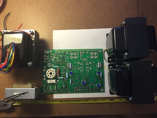 layout-a-02 by jeffdrouin, on Flickr
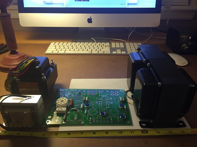 image by jeffdrouin, on Flickr
(B) (more spacious) 17 x 12 x 3 aluminum chassis (no cage for this size, would have to fabricate), with the OPTs behind the board, PT back left corner, choke, and cap on the left. Length and width can be smaller here.
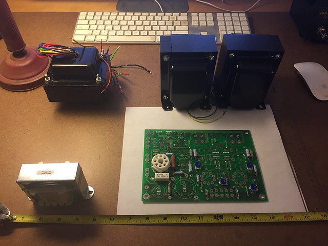 layout-b by jeffdrouin, on Flickr
Option A is the easiest, but I'm a little concerned about sandwiching the board between the magnetics, which are pretty close. Also not sure how the laydown PT might interact with board components, tubes, or choke.
And also, I've seen a lot of TSE builds in which Electra-Print OPTs are right next to each other with their laminations parallel, as in (A). I assume there is little to no magnetic interference between them with that arrangement?
Let me know what you think, and if there are other layouts I should consider.
Thanks!
Jeff
Here's what's going in it:
* Tubelab SE board w/300Bs
* Weber 2022798 laydown PT
* Electra-Print OPTs (5k:8ohm, 100mA, 15w)
* Triad C-14X choke (6 Henries, 200mA, 150 ohm)
* Motor run cap for C5
I've been sizing based on the availability of Hammond chassis/covers at Angela because I have small kids and want to make sure everything is well protected. I might have to go with different dimensions and make a cage, though.
(A) 16 x 8 x 3 aluminum chassis -- PT, choke, and future motor run cap on the left, board in the middle, OPTs on the right
layout-a-02 by jeffdrouin, on Flickr
image by jeffdrouin, on Flickr(B) (more spacious) 17 x 12 x 3 aluminum chassis (no cage for this size, would have to fabricate), with the OPTs behind the board, PT back left corner, choke, and cap on the left. Length and width can be smaller here.
layout-b by jeffdrouin, on FlickrOption A is the easiest, but I'm a little concerned about sandwiching the board between the magnetics, which are pretty close. Also not sure how the laydown PT might interact with board components, tubes, or choke.
And also, I've seen a lot of TSE builds in which Electra-Print OPTs are right next to each other with their laminations parallel, as in (A). I assume there is little to no magnetic interference between them with that arrangement?
Let me know what you think, and if there are other layouts I should consider.
Thanks!
Jeff
Jeff,
As far as I know, placing OPTs side by side with laminations in parallel will be ok - you should have the power transformer at 90 degrees to the OPTs and that looks fine in the layout.
Is the Hammond chassis cover tall enough to accommodate 300B tubes? If I am not wrong, the chassis cover height is 5.2", while a 300B tube (JJ datasheet linked) is taller:
http://www.hammondmfg.com/pdf/1451-30.pdf
http://www.thetubestore.com/lib/thetubestore/JJ-300B.pdf
.... Also not sure how the laydown PT might interact with board components, tubes, or choke.
Flat mount PT's are all I've used on my Tubelab amps, SSE and TSE, and I have observed no interaction with board components.
If you look at my TSE in the picture thread, that was later rebuilt to an SSE in the child resistant thread, you can see how compact both amps were built and how close the boards are to the magnetics. A lot closer spaced than on your 16 x 8 chassis.
Win W5JAG
EDIT : If you are going to use a Hammond cage, be advised that the perf sides have a "lip" that goes inwards about 1/8 or 3/16" of an inch ( don't recall off the top of my head. ) Doesn't sound like much, but when I rebuilt the TSE into the SSE and started fitting it for the cage, this was enough to necessitate a mandatory change of OPT's from Transcendars to the smaller Edcor's, with attendant filling of extra uneeded holes and drilling of new holes. Not a royal PITA, but an unexpected PITA that I did not anticpate.
That 16 x 8 chassis might be problematic with a cage and those huge OPT's. Just an FYI FWIW.
SECOND EDIT: as ZMan correctly notes, there is a height limit under the cage. I think 45's and 5930's would be OK. 300B's, I'm not so sure. Also, as you trap more heat under and close to the sides of the cage, touching the cage, while not a shock hazard, may be too warm to the touch.
Some of my thoughts and experience on this can be found here, and may or may not be useful to you:
http://www.diyaudio.com/forums/tubelab/245698-simple-child-resistant-sse.html
Last edited:
....
Is that OK, or should I try to fill the entire hole?
I think you should fill the entire hole. The solder tends to disappear over time.
Win W5JAG
Great, thanks for all these responses. This is very helpful, and I'll try to move the socket pins to the middle of the holes in order to make the solder adhere and fill better.
I found less expensive Bud Industries aluminum chassis on Amazon, and in dimensions like 17 x 12 x 3 that I think will work better to allow more space and cooling for these large components.
About the cage height: I'm planning to mount the PCB on common hardware screws with nuts and washers so as to make the height adjustable. That means I could lower the PCB to allow the 300Bs to fit under the cage. It would also be possible to shim the cage up a bit to make more room.
However, if I want something a little less nice than the circular-hole perforated metal, for $20 I can buy enough 22 ga sheet and expanded metal at Home Depot to make a 6-inch tall (or taller) cover, allowing more room between the cage and transformers. Would be very easy to cut with aviation snips and bend on my worktable edge.
2 more nuts & bolts questions:
* Will this thing get hot enough that I should use high temp primer and paint on the chassis & cage?
* Any recommendations for gauge and brand of solid copper hook up wire to use?
Thanks,
Jeff
FYI.
I bought a Hammond cage for my 10x17 SSE chassis. With 5AR4 and a pair of KT-88s, it became shockingly hot and now gathering dust.
Maybe 'extremely hot' would be more appropriate in this context. If you get both a high voltage jolt plus
burnt fingers you'd probably be in the hospital or graveyard at this time........
")
However, if I want something a little less nice than the circular-hole perforated metal, for $20 I can buy enough 22 ga sheet and expanded metal at Home Depot to make a 6-inch tall (or taller) cover, allowing more room between the cage and transformers. Would be very easy to cut with aviation snips and bend on my worktable edge.
It will not get so hot that you need to worry about high temperature paint. This is a tube amplifier - not an IC engine.
As to the size of hook up wiring, it depends on what the hook up wire is doing. For anything carrying current, the same or similar size as is used in the primary of your OPT's will be sufficient.
I'm not entirely sure about the material you are talking about from Home Depot, although I have a pretty good idea what it is.
When talking about protecting your kids, it seems to me the first thing you need to decide is what are the kids going to be protected from, heat or voltage? To ask this question is to answer it - touching something hot is usually not lethal, unpleasant if hot enough, but that's about it. A small child hitting a high enough voltage can potentially be one and done lethal. And that's why I didn't use the type of material you are talking about - if it is what I am thinking about it, it has pretty wide apertures and a conductive object could conceivably be pushed through it and hit a high voltage point. If there's a return path, well ....
So I went with the steel cage, with the small perforations, as I think the chances of something getting pushed through it are pretty much nil. That's also why my wiring under the chassis is in plastic wrap or out around the edges of the amp, to avoid something getting pushed up under there and abrading insulation and going hot.
If heat is the primary concern, then the material with the larger apertures will obviously cool better.
Heat management is something you need to think about on the front end, and not as an afterthought. If you just build it and slap a cage on it, it's not likely that will achieve a good result. I'm not all that familiar with 300B's but I'm surmising it's about a 40 watt tube, so a couple of those, plus your 5AR4, and the 5842's, probably a couple of hundred watts in heat right there. The TSE has some additional heat generating areas - the filament regulator on my TSE ran hot enough that even with a heatsink, I felt the need to mount a small fan directly on the heatsink. Then you have the powerdrive circuits, the bias regulators, etc., contributing additional heat. The PT will generate heat but you've wisely chosen a flat mount that will conduct a lot of it to the chassis and spread it around. The OPT's will soak up heat, but won't generate any of their own.
You may want to consider the addition, now or later, of an exhaust fan to pull hot air out of the amp, as you are considering your chassis layout. A large fan, running slow, will not be too noisy. A small fan running fast will be just the opposite. You may also want to consider just generating less heat in the first place. 45's will make less, 2A3's will be in the middle, relative to 300B's.
Looking forward to seeing your build.
Win W5JAG
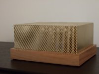
That ^^^^ looks nice.
I've found power switches, at least lighted ones, to be a bit of an attractive nuisance - flipping them on and off to watch the light go on and off, results in an unhappy life for rectifier tubes.
Ditto volume knobs - they make a toe hold for climbing .....
Kids are hard on stuff.
Win W5JAG
I've found power switches, at least lighted ones, to be a bit of an attractive nuisance - flipping them on and off to watch the light go on and off, results in an unhappy life for rectifier tubes.
Ditto volume knobs - they make a toe hold for climbing .....
Kids are hard on stuff.
Win W5JAG
Thanks for the very thoughtful response, Win. I'm planning to drill 1/4" holes in the chassis over the entire PCB, as well as the bottom plate except for under the PCB. in order to facilitate airflow. I'm hoping that would be adequate to keep the inside of the amp from overheating with something like a Hammond perforated cage on top.
My idea for a DIY cage is to use plain steel sheet metal for the sides and plain expanded steel for the top, painted in satin black. Thinking eggshell white for the chassis with a nice red pilot light and volume knob up front.
Everbilt 12 in. x 24 in. 22-Gauge Plain Sheet Metal-800617 - The Home Depot
Everbilt 24 in. x 1/2 in. x 12 in. Plain Expanded Metal Sheet-801417 - The Home Depot
The expanded at HD has 1/2" openings, which would allow small cylindrical objects to poke through, but I'm not too concerned about their doing that. You never know, of course, but I think it'd be OK. The power switch is going to be on the back where they are unable to reach right now.
My kids are 5.5 and almost 3, and are pretty good about not touching stuff that I set limits on. I'm more concerned about protecting them from burns than electric shock.
I don't know. I love the Hammond 17 x 10 cage but, playing around with 17 x 10 layouts with the newly arrived 300Bs (yes! early, and from China to boot), it's still going to be cramped. Workable, but a little tighter than I'd like.
I could always get that circular perforated steel to make a 17 x 12 cage ($27 from Grainger for a 30 x 40 sheet), like the one zman01 posted, but I wouldn't be saving much money over buying one commercially. It would just get me the size and the look I want.
Oh, and the hookup wire would be going from the input RCA jacks to the PCB and a volume potentiometer (I found 10K and 50K ALPS Blue Velvets that look promising).
If I understand aright, the OPTs have wires that would get soldered to the speaker binding posts.
Last edited:
For volume pots I've used these (were suggested to me in one of the threads) and found them pretty good:
Dact Type 21 Stepped Attenuator Potentiometer 50K 300B | eBay
Dact Type 21 Stepped Attenuator Potentiometer 50K 300B | eBay
Thanks for another great suggestion, zman01. I looked around and thought about an ALPS Blue Velvet 50K pot but ended up with the stepped attenuator. Seems like it should be quieter and have a more even channel volume balance.
w5jag, did you take your TSE out of mothballs? How was it?
Back to nuts and bolts (literally):
Do you guys do anything special to isolate mechanical vibration when mounting the power and output trannies? I'm afraid rubber or nylon washers would melt, but maybe adding something like that is overkill?
Also, since I'll have to purchase the hardware to mount the trannies and the PCB, are there any materials to avoid? Can I use galvanized or stainless steel? Too magnetic?
Last edited:
Jeff,
Never thought about washers for the transformers - I've always gone for a "screwed on tight and secure" fit. And haven't had a transformer that buzzes or rattles - a good quality well, made one should not do so. Hopefully your amp will not get hot enough to melt rubber/nylon. Maybe silicone washers?
Never thought about washers for the transformers - I've always gone for a "screwed on tight and secure" fit. And haven't had a transformer that buzzes or rattles - a good quality well, made one should not do so. Hopefully your amp will not get hot enough to melt rubber/nylon.
Maybe silicone washers?w5jag, did you take your TSE out of mothballs? How was it?
Oh, it's just a working board right now ( well, it worked when I pulled it from service five years ago ), with no present chassis to mount it on ( or in ) so putting it back in service will take a bit of effort.
An extremely nice, large, steel / plexiglass enclosure has dropped into my lap recently, so I'm thinking about using it drive some SV811's or SV572's, maybe 211's ( I think I have some 211's somewhere ), similar to George's 845 amplifier, but that will be a big learning curve for me.
I just use ordinary nuts, screws, and washers from the hardware store. Nothing special.
Win W5JAG
- Status
- This old topic is closed. If you want to reopen this topic, contact a moderator using the "Report Post" button.
- Home
- More Vendors...
- Tubelab
- Tubelab SE 300b Build Thread