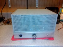
It's been about two years since I made any contribution to the Tubelab forum. For some time I've wanted to make a low power 6V6 SSE. The birth of our third child (almost three decades since the last  ), and the arrival of his toddling and exploratory time, made a child resistant SSE mandatory. The want and the need converged, and the result is a child resistant, low power, SSE, shown here.
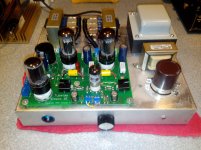
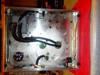
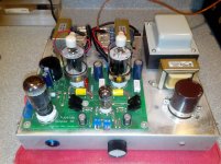
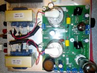
Kid protection is done the old fashioned way - an old school, perforated steel cage. These are an off the shelf item available from Hammond, in several sizes and finishes, including 12" x 10", a chassis size I already had on hand, mostly cut and drilled, the remnant of a 45 / 2A3 Tubelab SE, now dismantled. This made construction fast and easy. A few unneeded holes were filled on the donor chassis, the power transformer, a flat mount Utah of unknown vintage, was reinstalled. It is well suited for a low power SSE; it is heavy, loaded B+ output is 320 ish with a CLC circuit, and 275 ish with an LC circuit. It does not have screen voltage secondaries. Output transformers are the small Edcor XSE-15-8K, replacing the Transcendars that were used with the Tubelab SE.
A new SSE board was assembled almost in the usual manner; the dropping resistors in the CCS circuit were omitted because of the low B+ voltage. All components are top mounted for quick access for future modifications.The board is installed on top of the chassis, under the cage.
To keep heat down, initially I elected to use solid state rectification, and put a couple of silicon rectifier diodes on the board. An additional benefit of this was that the 5 volt secondary became available for other uses, including a low voltage supply for possible future solid state circuitry, or for a screen grid supply voltage. The former can be achieved by rectifying the output and running it into a voltage doubler or tripler for a solid state circuit, and the latter by combination with a second, small, filament transformer, thus:
120 : 5 = 5 : 120
and then rectifying and filtering the 120 volt AC output in the usual manner for screen voltage. Having done this previously in other projects, this yields output in the 170 - 180 volt range, suitable for small tubes like 2E26, 6BQ6, 6W6 and 6Y6 that require a low screen voltage when used as pentodes.
Later, I did decide to install a tube rectifier. To keep the 5 volt secondary free, I chose a 6AX5GT. This was selected as it can be fitted on the SSE board with no destructive modifications, needing only a few jumpers on the socket traces to rearrange the pins, and 6 volt filament power ran to pins 2 and 7 on the socket. This tube has low noise operation, and power output comparable to the 5Y3. The 6X5 can also be used without further modification, however, it has only about 65% of the power output of the 6AX5. Both of these tubes are plentiful and inexpensive.
Another oddball feature is the 3.5mm stereo phone jack on the front panel as a secondary audio input. This is wired in parallel with the rear panel inputs, a dubious practice from a technical standpoint, but one that works well in actual practice, and is quite convenient.
Presently, the power supply uses a 4.7uF first capacitor and a 10H inductor. B+ is 320 ish, depending on the power tubes. The cathode resistors are 680 Ohms. THe feedback at the output tubes is ultralinear. Cathode feedback is not (yet) enabled. This puts 6F6 at about 11 watts, 6V6 at about 10 watts, and 6K6 at about 11 watts (6K6 is an 8 watt tube). I have not tried 6G6 yet, or 6W6 and 6Y6, as the latter two require a low screen voltage and pentode wiring, or triode wiring. 6L6, 6L6GA, 6L6GB, and 5881 could also be used.
A few pictures are attached. It is rough looking, being hastily thrown together out of materials on hand, the cage being the only part I had to acquire. The large, off board, filter cap is not presently connected. It fills a hole where a meter resided in the Tubelab SE. I had intended to use it, but the amp is stone cold silent on 96db ish speakers without it, so it remains unconnected. Paint is a possibility, if the demands on my time relent at some point.
This is a nice sounding amp; the 6V6 is one of the finest sounding audio tubes, imho. It has been in service a couple of months without issue.
Win W5JAG
), and the arrival of his toddling and exploratory time, made a child resistant SSE mandatory. The want and the need converged, and the result is a child resistant, low power, SSE, shown here.Kid protection is done the old fashioned way - an old school, perforated steel cage. These are an off the shelf item available from Hammond, in several sizes and finishes, including 12" x 10", a chassis size I already had on hand, mostly cut and drilled, the remnant of a 45 / 2A3 Tubelab SE, now dismantled. This made construction fast and easy. A few unneeded holes were filled on the donor chassis, the power transformer, a flat mount Utah of unknown vintage, was reinstalled. It is well suited for a low power SSE; it is heavy, loaded B+ output is 320 ish with a CLC circuit, and 275 ish with an LC circuit. It does not have screen voltage secondaries. Output transformers are the small Edcor XSE-15-8K, replacing the Transcendars that were used with the Tubelab SE.
A new SSE board was assembled almost in the usual manner; the dropping resistors in the CCS circuit were omitted because of the low B+ voltage. All components are top mounted for quick access for future modifications.The board is installed on top of the chassis, under the cage.
To keep heat down, initially I elected to use solid state rectification, and put a couple of silicon rectifier diodes on the board. An additional benefit of this was that the 5 volt secondary became available for other uses, including a low voltage supply for possible future solid state circuitry, or for a screen grid supply voltage. The former can be achieved by rectifying the output and running it into a voltage doubler or tripler for a solid state circuit, and the latter by combination with a second, small, filament transformer, thus:
120 : 5 = 5 : 120
and then rectifying and filtering the 120 volt AC output in the usual manner for screen voltage. Having done this previously in other projects, this yields output in the 170 - 180 volt range, suitable for small tubes like 2E26, 6BQ6, 6W6 and 6Y6 that require a low screen voltage when used as pentodes.
Later, I did decide to install a tube rectifier. To keep the 5 volt secondary free, I chose a 6AX5GT. This was selected as it can be fitted on the SSE board with no destructive modifications, needing only a few jumpers on the socket traces to rearrange the pins, and 6 volt filament power ran to pins 2 and 7 on the socket. This tube has low noise operation, and power output comparable to the 5Y3. The 6X5 can also be used without further modification, however, it has only about 65% of the power output of the 6AX5. Both of these tubes are plentiful and inexpensive.
Another oddball feature is the 3.5mm stereo phone jack on the front panel as a secondary audio input. This is wired in parallel with the rear panel inputs, a dubious practice from a technical standpoint, but one that works well in actual practice, and is quite convenient.
Presently, the power supply uses a 4.7uF first capacitor and a 10H inductor. B+ is 320 ish, depending on the power tubes. The cathode resistors are 680 Ohms. THe feedback at the output tubes is ultralinear. Cathode feedback is not (yet) enabled. This puts 6F6 at about 11 watts, 6V6 at about 10 watts, and 6K6 at about 11 watts (6K6 is an 8 watt tube). I have not tried 6G6 yet, or 6W6 and 6Y6, as the latter two require a low screen voltage and pentode wiring, or triode wiring. 6L6, 6L6GA, 6L6GB, and 5881 could also be used.
A few pictures are attached. It is rough looking, being hastily thrown together out of materials on hand, the cage being the only part I had to acquire. The large, off board, filter cap is not presently connected. It fills a hole where a meter resided in the Tubelab SE. I had intended to use it, but the amp is stone cold silent on 96db ish speakers without it, so it remains unconnected. Paint is a possibility, if the demands on my time relent at some point.
This is a nice sounding amp; the 6V6 is one of the finest sounding audio tubes, imho. It has been in service a couple of months without issue.
Win W5JAG
Attachments
As you note, if it's too hot to touch, it's not suitable to be around kids.
Two KT-88's, plus a 5AR4, and a 12AT7 - probably a couple of hundred watts in heat right there, before you even get to the heat generated by the power transformer. If it's undersized, it just makes things worse. An exhaust fan might help you, but it still may be too much heat, in too small a space, even with a fan.
That's why mine is sized the way it is. Two twelve watt tubes, a 12AT7, and a 6AX5, maybe sixty five watts total heat from the tubes, and quite a bit of empty space between the top of the tubes and the cage. The power transformer is oversized, so it runs cool to the touch, and it's a flat mount - much of the minimal heat it generates is sinked to the chassis and spread around, rather than cooking a spot on top of it.
My cage runs at about room temp, even after many, many, hours of use. Cool enough that I could probably go up to the 19 watt class of tubes, like 6L6 and 5881. That's probably about the limit of the 6AX5 rectifier, although I have diodes on the board, if need be.
When I was first pondering this, I considered using an LMB Heeger CO-6 ( 9 x 11 x 6 ) cabinet. The advantage of this was that I had one on the shelf*. The disadvantage was that heat management looked dicey, at best, and I would have to use an upright power transformer, or an undersized flat mount, and the output transformers would have to go on the back of the cabinet, under a sub cabinet. It would have been do-able, probably, with a small exhaust fan, but for long term reliability and simplicity, I just went with the cage. It's working out very well.
If I were going to do it with a "big" amp, I would start with the biggest chassis and cage Hammond makes ( 17 x 10 ?) and make provisions in advance for an exhaust fan, in the event chassis size alone was not sufficient to dissipate the heat.
Win W5JAG
* I use a lot of the LMB Heeger cabinets - they are a decent looking off the shelf product. I have a scratch built two meter rig in a C0-4, my original SSE was built on a C0-1 chassis that originally was used for a scratch built 75 meter ssb transceiver ( my second big project ). Ironically, while rummaging around in the warehouse of junk a few weeks ago, I found the C0-1 cabinet for the chassis, so the old warhorse original SSE may yet ride again, in a fully enclosed C0-1 cabinet. Or maybe the Tubelab SE will be resurrected and go in that cabinet as a child resistant TSE.
alternate tube data
Tubelab provides model data for the 6V6 in the SSE. For good reason, most low power variants of the SSE likely use 6V6. Here is some data on alternate tubes for use in low power SSE amps, specifically the above described child resistant SSE.
6Y6: Ordinarily, I would think this tube unsuitable at the voltages present in my child resistant SSE. It specs at low plate voltage, and even lower screen voltage. However, an application note in an old Acrosound Transformer catalog describes superlative performance of this type in a push pull ultralinear configuration, at voltages similar to my amp. 6Y6 has a large heater current requirement - 1.25 Amps, approximately three times that of the 6V6.
The 6Y6 I had on hand are JAN GE 6Y6GT, 1966 vintage, previously unused. The spec data given below is from the GE data sheets. I have seen different specs. but went with the GE data, since my tubes are GE.
6Y6 in child resistant SSE, measured
Ultra Linear configuration
anode 287 spec 200
screen 290 spec 135
cathode 41.5
Rk = 680
(41.5/680)=0.061 (246)(0.061)= 15 watts spec 12.5 watt
This is serious spec busting (this is the Tubelab forum, after all) and a cathode resistor of 820 ohms, perhaps larger, would probably bring this tube into spec. That said, they don't show any distress at 15 watts, no sign of color on the plates, or other issues at the elevated voltages found in my amp.
6W6: 6W6 also has a large heater current requirement - 1.25 Amps, approximately three times that of the 6V6.
The 6W6 I had on hand are 70's vintage, coin base GE 6W6GT, previously unused. The spec data given below is from the GE data sheets. I have seen different specs. but went with the GE data, since my tubes are GE.
6W6 in child resistant SSE
Ultra Linear configuration
anode 306 spec 300
screen 309 spec 150
cathode 33
Rk = 680
(33/680)=0.049 (273)(0.049)= 13.375 watts spec 10 watts
This is more spec busting, and a cathode resistor of 820 ohms, perhaps larger, would probably bring this tube into spec. They do not show any distress at 13 watts, no sign of color on the plates, or other issues at the elevated voltages found in my amp.
I would not consider using these in any configuration than ultra linear at these voltages. The screens have too low a rating for pentode or triode at these voltages. I have used both as triodes at 210 or so volts with out any issues and with good results.
Russian 6F6S: These are sold on Ebay as an analog to the American 6F6 and mine measure remarkably similar. I believe they can be considered as 6F6 for all intents and purposes. Mine are the small shoulder type, early 60's vintage. I am not entirely sure on the specs; I don't read cyrillic.
anode 333 spec 410
screen 334 spec 315
cathode 25
Rk = 680
(25/680) = .037 (308)(.037) = 11.4 watts spec 12 watts
These tubes sound good. They are somewhat expensive compared to american 6F6.
Russian 6L6GT: aka 6P3S, These are sold on Ebay as 6L6GT, an analog to the American 6L6, and they are a reasonable analog to the original 19 watt 6L6. I believe they can be considered as 6L6 or 6L6GA (NOT 6L6GB or GC) for all intents and purposes. Mine are Reflector made, unknown vintage. I am not entirely sure on the specs; I don't read cyrillic.
anode 314 spec 400?
screen 317 spec 300?
cathode 33
Rk = 680
(33/680) = .0485 (281)(.0485) = 13.6 watts spec 20.5 watts?
I have written bad things about these tubes before; I take it all back. I think they sound terrific. I have put probably over a thousand hours on mine, they show no degradation, sound terrific, and are a great value.
One other note: my GE 6AX5GT rectifier shows visible signs of taking a beating, but does not show any evidence of electrical degradation thus far. The type I use has the innards of a 6087/5Y3WGTB.
Two other small types might work: 6U6 and 6M6. I have some 6U6 in my warehouse, but had none here at the house to test. I have never seen 6M6. I question whether it actually exists, or was used here in the U.S.
Hopefully, this data will help other builders of low power SSE.
Win W5JAG
Last edited:
Thanks for the info W5JAG. I have a second SSE for use with 6V6, 6K6 and 6F6 tubes. B+ with a 5AR4 rectifier is 340V and
with a 5V4 rectifier is around 320V which is what I use mostly with these tubes.
I have some RCA and Sylvania 6Y6G tubes. Using a GE 6087 rectifier I get a B+ of around 290V so I tried these tubes in there
with 900 ohm cathode resistors. After many hours of use I see or hear no indications of damage to the 6Y6 tubes.
From memory the measurements I took were about 5% above spec.
I tried triode config for a short while but switched to UL because this sounded better with my speakers
which are only rated at 89db efficiency but presents a very tube friendly load.
I've been using UL mode ever since. I really have to get a pair of good high efficiency speakers.
which are only rated at 89db efficiency but presents a very tube friendly load.
I've been using UL mode ever since. I really have to get a pair of good high efficiency speakers.
Some additional data
6BQ6GTB in child resistant SSE
6BQ6 also has a large heater current requirement - 1.25 Amps, approximately three times that of the 6V6. This is a pair of Tung Sol tubes, data is from a GE data sheet, my Tung Sol books are boxed from a move.
Ultra Linear configuration
anode 282 spec 600
screen 286 spec 200
cathode 40
Rk = 680
(40/680)=0.059 (242)(0.059)= 14.25 watts spec 11 watts
It's easy to see where the 6AX5 rectifier runs out of gas and experiences a pretty significant voltage sag beyond its spec - excluding the current drawn by the 12AT7, it's somewhere just past 49 ma per power tube, or in excess of about 13.5 watts. Assuming 20 ma or so for the 12AT7, that looks to be right in line with the data sheets.
2E26 and 6146 in the Child Resistant SSE
Transmitting tubes 2E26 and its higher powered follow on, 6146, are easily adapted to the SSE board. Details can be found in an earlier thread in this subforum; briefly plate voltage must be sent to the anode cap, screen voltage must be applied to pin 3 of the power tubes, and pin 4 of the power tubes must be left open as it is internally connected to the cathode in these types. Because of the unique configuration of the SSE board, making these changes is trivial.
2E26 in the child resistant SSE:
The 2E26 has an 800 ma heater current. This is almost double the current drain of the 6V6. Data is taken from the 1947 RCA data sheet.
Ultra linear configuration:
Anode 320 spec 300
Screen 323 spec 200
Cathode 28
Rk = 680 ohms.
(28/680) = .041 (.041)(292) = 12 watts. The specification for continuous duty (CCS) service is 10 watts maximum.
I continue to be impressed at how adaptable the 2E26 is to audio amplifier service. They always seem stable, tolerant of reasonable out of spec operation, and just sound good.
6146B in the child resistant SSE:
The 6146 has an 1250 ma heater current. This is almost triple the current drain of the 6V6. Data is taken from the 1964 RCA data sheet.
Ultra linear configuration
Anode 275 spec 600 (CCS)
Screen 279 spec 250 (CCS)
Cathode 44
Rk = 680
(44/680) = .064 (231)(.064) = 14.75 watts. The plate dissipation spec for continuous duty (CCS) is twenty watts. It is well within all specifications. It works well and sounds very good in this configuration. RCA deemed it a compact powerhouse and it is an apt description.
Several things are apparent: First, the high perveance characteristic of 6146 - it's happily sucking down almost 65 milliamps cathode current at a mere 231 volts across the tube. It's a sweep tube and needs to be treated as such.
Second, the extreme voltage sag of the 6AX5 rectifier - when it runs past its current spec, the output voltage just falls off a cliff.
Third, 2E26 is typically portrayed as just a low power 6146, but it really doesn't behave much like the 6146. In all configurations, 2E26 behaves more like an ordinary audio tube. It has a low screen voltage rating, but it doesn't act much like a sweep tube, whereas 6146 is very much a sweep tube.
Win W5JAG
Attachments
Last edited:
I have about 600 hours now on the 2E26 tubes under the operating conditions last described.
I put them in the TV-7/D tonight, and both measured about 12% higher than when they went in service. Transconductance was, literally, almost off the scale. So, running the tubes at the max CCS power isn't hurting them.
The 6AX5 rectifier is still hanging in there. It tests marginally weaker ( about 2% ) than when I last tested it, and looks like it was rode hard and put up wet, but remains very serviceable.
Win W5JAG
2E26 Service Life
This morning I checked the tubes again.
The 2E26 showed significant loss since I last tested them, when they literally pegged the needle on my TV-7D, but they still test strong enough to be passed off as new, had I not known of their service history.
This SSE is the PA in our home entertainment system and it runs long hours, typically it is on whenever someone is home and awake. At this point I estimate this pair of 2E26 are approaching 2000 hours of in service life. They are still running UL, wth screen voltage significantly in excess of the rating.
These 2E26 are running about 12 watts. The CCS rating for 2E26 is 10 watts. If there is anything that can be learned from a sample of only one pair of tubes, it is that the CCS rating looks to be conservative when applied to audio amp service.
The 12AT7 also has about 2000 hours on it at this time. It tested right at the absolute minimum for a good tube. This is not surprising - the SSE runs these tubes hard. For anyone interested, it's a non mil grade (real) Mullard. It was left in service.
The GE 6AX5 (6087 guts) rectifier has settled in, and shows no decline, electrical or visual, since I last checked it.
Win W5JAG
Last edited:
Had the tester out to check a bunch of 5842 and 417A today, so checked these as well.
Both 2E26 tested similar to their last test - they show zero adverse effect from being run at 20% in excess of the RF CCS specification. I think this is also good evidence that the cooling under the cage is completely adequate for this power level.
The Mullard 12AT7 tested noticeably better. I was prepared to replace it, but left it in service.
I did not test the 6AX5.
Win W5JAG
6AR6 in the SSE
6AR6 ( and 6098 and 6384 ) are not pin compatible with the sockets in the SSE. A socket adapter is required.
Which is a shame, because 6AR6 looks to be a stellar performer in the low power, low voltage, SSE.
6AR6 and 6098 look identical to a Tung Sol 5881, except they are not a 5881. Compared to the 5881, 6AR6 has a higher filament current, much higher plate voltage rating, and somewhat lower screen voltage rating. Power is also lower, 19 watts in the 6AR6.
In my child resistant low power SSE, ultra linear configuration, the typical 6V6 runs about 1.2 watts out into a 9 ohm load; the low power 6L6's and 5881 run about two watts. 6AR6 does 3.5 watts before any flattening of the sine wave can be observed on the scope. With a solid state rectifier in place of the 6AX5, I saw 6 watts before clipping. It does almost twice the power output, at about 30 per cent less distortion, than a low power 6L6 type at the same power and voltages.
The numbers, with 6AX5 rectifier:
plate voltage 322 - spec 565
screen 322 - spec 300
Cathode 35
With a 680 ohm resistor, that's 14 watts if my arithmetic is correct. The rating is 19 watts.
Win W5JAG
After building the Heath AA-1 and using it to check out the TSE 801, naturally I ran the child resistant SSE on it.
Since I built the amp for 6V6, that was the first tube I looked at, and pretty quickly saw that my power supply choices just weren't working well.
Here is what I saw with the holy grail of 6V6, the Bendix 5992, with Vp = 309; Vs=310; and Vk=21. Rk is 680 ohms. At 1.5 watt output, IMD was 100%; at 1.0 watt output IMD was 56%; at 0.5 watt IMD was 32%, and 0.10 watt it was 9%. This was in ultra linear with cathode feedback.
Now, the AA-1 uses the SMPE IMD test, which I think is a really difficult test for any single ended amplifier, but the above results were a lot worse than I expected. Clearly, I had made some bad choices in voltages and Rk, so I set about to try and make some better choices. Long story short, I couldn't make much improvement just by moving the B+ voltage around by fiddling with the tubes/solid state rectifier.
Finally, I pulled the rectifier altogether, pulled the cathode resistor, and hooked it up to an external supply, where I could really move the voltage around, and play with different cathode resistors, and just watch as the IMD varied.
After a lot of fiddling, what I found is that, with 5992, at 270 volts on the plate, best IMD was at 13.45 volts on the cathode. A little bit of cathode voltage difference, unfortunately, can translate into a pretty big IMD difference, and different 6V6's seem to like different points. A GE 6V6, for example, performed best at 12.75 volts on the cathode, where it did 2.5% IMD at 100 mw, which was my test point, as I felt that with my 96dB speakers, I would rarely need more power than that. I found that optimizing at one power level was not necessarily optimum for a lesser level, so some choice was involved.
Having found out where I needed to be, I set about translating that to my SSE chassis. The only way to get the B+ down to 270 would be to use a choke input supply, but I could not get that to work. I have a 10H choke on the amp, but it's only rated for 100 ma. I could hit my B+ target, and could hit my cathode voltage target, but it was clear to me that the amp was unstable. My WAG is that I was sucking so much current, my choke was falling below the critical inductance level.
At this point, I was more than a little irritated that the bliss of ignorance had been shattered. I did eventually find one point that would work with my existing power supply components: Vp = 316; Vs=320; and Vk=12.0. Rk 193 ohms. At 1.0 watt output IMD was 13%; at 0.5 watt IMD was 9.1%, at 0.10 watt it was 2.6%., and at 0.05 watt it was 1.75%. This was in ultra linear with cathode feedback. Disabling cathode feedback increased the IMD slightly.
Of course, if one does the math, that is smoking hot, even by the standards of this forum; 19 watts through a 6V6. The tube was a humble GE 6V6 that showed absolutely no distress at 19 watts.
For those interested, the GE 6V6 looks to be a better performer than the 5992 from a distortion standpoint.
So it looks like my options at this point are: I can rework my power supply, maybe incorporating a fixed bias supply; I can do nothing and just run 6V6's smoking hot - I have a lot of them; or I can find a tube that works better with my build.
Win W5JAG
Last edited:
an unlikely tube comes to the rescue
Here is a tube that works really well, without any changes other than adding a solid state rectifer in place of the 6AX5.
At a plate voltage of 341 volts; screen voltage of 346 volts; the cathode voltage was 55 volts and cathode current was 80 ma. Power was 23 watts. This is in ultra linear with cathode feedback.
Look familiar? It's the tube widely thought to be useless for single ended audio.
The 6146B.
Here are the IMD numbers it put up at the above points:
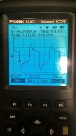
At 2 watts output, IMD was 15%; At 1 watt output, IMD was 8%; At 0.5 watt output, IMD was 5%; and at 0.1 watt, it did 2.4%. Clean sine wave output was 15 volts p-p, or 3.5 watts.
That performance rivals the TSE 801, when it is running at 40 mils. Indeed, the cathode feedback cuts about 2dB of power, without that 6146B would equal the power output of the 801 amp.
It's entirely possible these numbers can be improved on. I haven't done a thing to try to optimize it.
Below are a few scope shots. It clips assymetrically on the bottom. The 10Khz square wave performance of the Edcor XSE 5K transformer is terrible. I have seen this same pattern with every tube I have looked at. It is not unique to 6146.
Win W5JAG
Here is a tube that works really well, without any changes other than adding a solid state rectifer in place of the 6AX5.
At a plate voltage of 341 volts; screen voltage of 346 volts; the cathode voltage was 55 volts and cathode current was 80 ma. Power was 23 watts. This is in ultra linear with cathode feedback.
Look familiar? It's the tube widely thought to be useless for single ended audio.
The 6146B.
Here are the IMD numbers it put up at the above points:
At 2 watts output, IMD was 15%; At 1 watt output, IMD was 8%; At 0.5 watt output, IMD was 5%; and at 0.1 watt, it did 2.4%. Clean sine wave output was 15 volts p-p, or 3.5 watts.
That performance rivals the TSE 801, when it is running at 40 mils. Indeed, the cathode feedback cuts about 2dB of power, without that 6146B would equal the power output of the 801 amp.
It's entirely possible these numbers can be improved on. I haven't done a thing to try to optimize it.
Below are a few scope shots. It clips assymetrically on the bottom. The 10Khz square wave performance of the Edcor XSE 5K transformer is terrible. I have seen this same pattern with every tube I have looked at. It is not unique to 6146.
Win W5JAG
Attachments
Since 6146B worked so well, I thought 6BQ6 might as well. It did massively better than the conventional audio tubes in my amp, as it is currently configured, but was bested by 6146B. For these tubes, I used the 6AX5 rectifier.
This is for a "Shield" brand 6BQ6. I don't know much about this brand, other than they were a reseller, maybe of factory seconds. These are marked 6BQ6GTB, but they are the bigger variant, a little less beefy than a 6DQ6. I can't identify who actually made them.
This is in ultra linear with cathode feedback.
Plate voltage of 290 volts; screen voltage of 293 volts; cathode voltage was 40 volts and cathode current was 59 ma. Power was 15 watts.
Here are the IMD numbers it put up at the above points:
At 1 watt output, IMD was 13%; At 0.5 watt output, IMD was 10%; at 0.1 watt, IMD was 3% and at 0.05 watt, it did 2.9%. I did not test it for power output.
This is for Tung Sol brand 6BQ6. These are the usual small bottle 6BQ6GTB.
This is in ultra linear with cathode feedback.
Plate voltage of 288 volts; screen voltage of 292 volts; cathode voltage was 42 volts and cathode current was 62 ma. Power was 15 watts.
Here are the IMD numbers it put up at the above points:
At 1 watt output, IMD was 17%; At 0.5 watt output, IMD was 11%; at 0.1 watt output, IMD was 4.1% and at 0.05 watt, it did 3%. I did not test it for power output.
It's entirely possible these numbers can be improved on. I haven't done anything yet to try to optimize them.
I ran the 6146B for the last several weeks, and have had the Shield 6BQ6 in it for the last week.
Win W5JAG
I swapped the Hammond 10 H 100 ma choke for a Hammond 5H 150 ma choke and re ran the Shield 6BQ6. The improvement was significant
This is still in ultra linear with cathode feedback.
Plate voltage of 293 volts; screen voltage of 299 volts; cathode voltage was 40 volts and cathode current was 59 ma. Power was 15 watts.
Here are the new IMD numbers it put up:
At 1 watt output, IMD was 10%; At 0.5 watt output, IMD was 6.2%; at 0.1 watt, IMD was 2.4% and at 0.05 watt, it did 1.7%.
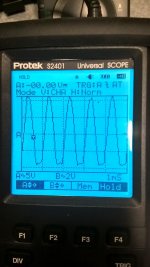
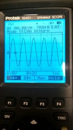
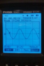
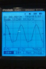
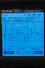
Undistorted single tone output was 1.6 watts. They still clip assymetrically. The sine wave is 1KHz. The "square" wave is 10KHz.
So, that was an easy change that drove things in the right direction. I haven't had time to look at anything other than the one 6BQ6 since doing the swap. Sorry the pics suck - cheap cell phone was all I had on me at the time.
Win W5JAG
This is still in ultra linear with cathode feedback.
Plate voltage of 293 volts; screen voltage of 299 volts; cathode voltage was 40 volts and cathode current was 59 ma. Power was 15 watts.
Here are the new IMD numbers it put up:
At 1 watt output, IMD was 10%; At 0.5 watt output, IMD was 6.2%; at 0.1 watt, IMD was 2.4% and at 0.05 watt, it did 1.7%.
Undistorted single tone output was 1.6 watts. They still clip assymetrically. The sine wave is 1KHz. The "square" wave is 10KHz.
So, that was an easy change that drove things in the right direction. I haven't had time to look at anything other than the one 6BQ6 since doing the swap. Sorry the pics suck - cheap cell phone was all I had on me at the time.
Win W5JAG
Attachments
- Status
- This old topic is closed. If you want to reopen this topic, contact a moderator using the "Report Post" button.
- Home
- More Vendors...
- Tubelab
- A Simple Child Resistant SSE