My SSE is currently the basic triode config with a choke, aux cap, tube and
solid state rectifier with a switch. No volume pot but I plan to install one
later. No CFB at this time. The board is grounded via one RCA input as per
Tubelab's wiring diagram.
With a cd player connected the amp is playing fine, clear and natural with
complete silence between tracks. However, with nothing connected to the
RCA inputs there is an obvious AC hum, the hum goes away as soon as the
player is connected but NOT powered on.
Additionally when I plug in my vacuum tube preamp without turning it on
the hum is there but when I turn on the preamp the hum fades away to
silence. Turning up the volume control and with ears close to the speakers
there is just a faint electronic noise.
So, with the above in mind is the hum due to grounding the board via the
RCA input or is there another reason ?
Sounds like you hit it on the head. It must have something to do with the rca. I really don't have a technical explanation, so hopefully someone else can provide insight. Maybe the CD player or preamp complete an otherwise open ground?
I grounded mine with one of the PT bolts. To it I connected the speaker post grounds and the board via one of the two connectors that the HV CT connects to. The bolt is then connected to the IEC ground. I found this gave me the shortest ground wires.
I have no hum unless the volume is pegged and I've got my ears on the speakers. Even then, I don't think what I hear is actually AC related.
Also, are your Rca's isolated from the chassis and are their grounds going to the board?
Yes my RCA's and speaker jacks are isolated from the chassis, I confirmed
this with a multimeter.
Below is the wiring diagram I used, my star ground is a transformer bolt
which is wired to the IEC ground pin. The chassis and everything bolted
to it is grounded via the star ground. Right now I am not using a volume
pot, my input goes directly to the board.

Sounds like you hit it on the head. It must have something to do with the rca. I really don't have a technical explanation, so hopefully someone else can provide insight. Maybe the CD player or preamp complete an otherwise open ground?
I grounded mine with one of the PT bolts. To it I connected the speaker post grounds and the board via one of the two connectors that the HV CT connects to. The bolt is then connected to the IEC ground. I found this gave me the shortest ground wires.
I have no hum unless the volume is pegged and I've got my ears on the speakers. Even then, I don't think what I hear is actually AC related.
I should try grounding the board like you have done and remove the ground
wire connecting the RCA input to the star ground.
So, you have the HV CT and one of the wires from the auxiliary cap
connected to these two terminals (T1-RED-YEL) then another wire in
one of these same terminals grounds the board via the star ground ?
Last edited:
That is correct. It is either of the two green colored connectors on the left side of the board in the diagram in your last post. If your inputs are isolated, this would be pretty simple to try. It sounds like you've done everything the same way I have otherwise.
Thanks, I'll do that later this evening after work.
Are the two input pairs tightly twisted? And do the pairs stay physically close together? They should probably be in a single shielded dual twisted pair cable.
What happens if you short the rca jack grounds together, with no source connected (while you hear hum)? And what if you short only the center conductors, at the jacks? And what happens if you short each rca ground to chassis, and if you short both of them to the chassis?
What else is on the board? Are there power grounds that are sharing the input ground conductor, to go to the star ground??
That is correct. It is either of the two green colored connectors on the left side of the board in the diagram in your last post. If your inputs are isolated, this would be pretty simple to try. It sounds like you've done everything the same way I have otherwise.
I wish I could report success but none. I was so confident this would fix the
problem.
I removed the ground wire connecting the RCA to the star ground. The board
is now grounded at one of the terminals where the HV CT is connected. I
confirmed again that the RCA jacks are isolated from the chassis. Powered
on and after about a twenty seconds warm up the hum is still there. When I
plug in my cd player the hum is gone and music is playing very well.
Probably has something to do with the input wiring.
Are the two input pairs tightly twisted? And do the pairs stay physically close together? They should probably be in a single shielded dual twisted pair cable.
What happens if you short the rca jack grounds together, with no source connected (while you hear hum)? And what if you short only the center conductors, at the jacks? And what happens if you short each rca ground to chassis, and if you short both of them to the chassis?
What else is on the board? Are there power grounds that are sharing the input ground conductor, to go to the star ground??
The two pairs of input wires are tightly twisted throughout their lengths. The
pairs are separated by about 3/4 inch but at the ends towards the board it's
over an inch. They are kept well away from the heater and HV wires.
Maybe later on I should try shielded wires. Many of the other
builders here use unshielded wire without problems.
I'll try lightly twisting the two pairs of wires and see what happens.
Later this evening I'll try the other things you suggested about shorting the
RCA grounds as well as the center conductors. I assume doing this will
cause no harm ?
The board has been successfully used by many others over the past seven
years so there is no issue with the grounding scheme. Here is a link to
the schematic -
Schematic | Tubelab
Last edited:
I'll post a picture of my amp wiring later today for you. It might help. I did twist the input pairs and used unshielded wire. What's the sensitivity on your speakers? Even George himself said he had to futz with hum when using his original with extremely high sensitivity horns (like 100db+).
In addition to gootee's suggestions, if you have enough slack in the wiring, you might try removing the RCAs from the chassis, just to make sure the isolation washers are doing their job. Could be a burr in the holes or something that's messing with your ground scheme. Certainly sounds like an issue related to the jacks.
For what it's worth, I used these:
Chassis Mount RCA Jack Pair 091-1120
I'll post a picture of my amp wiring later today for you. It might help. I did twist the input pairs and used unshielded wire. What's the sensitivity on your speakers? Even George himself said he had to futz with hum when using his original with extremely high sensitivity horns (like 100db+).
In addition to gootee's suggestions, if you have enough slack in the wiring, you might try removing the RCAs from the chassis, just to make sure the isolation washers are doing their job. Could be a burr in the holes or something that's messing with your ground scheme. Certainly sounds like an issue related to the jacks.
For what it's worth, I used these:
Chassis Mount RCA Jack Pair 091-1120
My speakers are not very efficient. I have three pairs, 2 are diy, and they're
between 86 and 88db. Right now I have the 86db ones connected because
they're the cheapest. My output tubes are EL34.
My RCA's are the same as those. I've confirmed with a multimeter that
they're isolated from the chassis but no harm in trying your suggestion,
I'm not sure I have enough slack though.
This evening I'll be doing the checks Gootee suggested, I believe these
should be useful. I'm sure the RCA jacks or the wiring connection is the
cause of my problem.
Are the two input pairs tightly twisted? And do the pairs stay physically close together? They should probably be in a single shielded dual twisted pair cable.
What happens if you short the rca jack grounds together, with no source connected (while you hear hum)? And what if you short only the center conductors, at the jacks? And what happens if you short each rca ground to chassis, and if you short both of them to the chassis?
What else is on the board? Are there power grounds that are sharing the input ground conductor, to go to the star ground??
The two pairs of input wires are now twisted a few times and are close
together but the hum is still there.
With the amp powered on without a source connected and shorting at the
jacks -
Shorted both grounds together and still humming.
Shorted each ground to chassis and still hums.
Shorted both grounds to chassis and still hums.
Shorting the left center conductor and hum STOPS
Shorting the right center conductor and hum STOPS.
Hope this gives you a clue to the problem.
Did the hum get worse for any of those shorting conditions?
Also, to what did you short each center conductor? Can you also give the result for shorting each center conductor to its own rca gnd, and to only the other rca ground, and to only the chassis, and to only the other center conductor?
Also, to what did you short each center conductor? Can you also give the result for shorting each center conductor to its own rca gnd, and to only the other rca ground, and to only the chassis, and to only the other center conductor?
Did the hum get worse for any of those shorting conditions?
Also, to what did you short each center conductor? Can you also give the result for shorting each center conductor to its own rca gnd, and to only the other rca ground, and to only the chassis, and to only the other center conductor?
The hum did not get louder. The hum is a low level hum.
When I am shorting the center conductor and only one end of the wire
is touching it the hum gets much louder but when the other end makes
contact with ground the hum is gone.
Shorting either center conductor to its own ground and then to chassis
ground result in no hum.
Shorting both center conductors together gives a louder hum.
Maybe it is just the ac wiring pairs not being twisted well-enough (i.e. not all the way to each end and/or not enough turns per inch). If there are any single ac conductors, running alone, for example, that would then form a large bit of "enclosed loop area" and would emit a time-varying magnetic field, which would induce hum in every other loop and conductor pair that has any enclosed loop area.
That's why a photo of the actual build would be helpful.
That's why a photo of the actual build would be helpful.
Maybe it is just the ac wiring pairs not being twisted well-enough (i.e. not all the way to each end and/or not enough turns per inch). If there are any single ac conductors, running alone, for example, that would then form a large bit of "enclosed loop area" and would emit a time-varying magnetic field, which would induce hum in every other loop and conductor pair that has any enclosed loop area.
That's why a photo of the actual build would be helpful.
I'll try to get a photo posted, never did this before.
I've twisted all the wiring pairs, HV wires and heater wires.
They're about two turns per inch.
I cannot twist the power transformer primary wires because the IEC
adaptor is on a rear panel and the power switch is on the front panel.
Yeah, that switch wiring is exactly what was worrying me, after I looked at the diagrams. You would have wanted to twist everything, anyway, i.e. from the rear panel to the transformer and then from the transformer to the switch. At the least, even if not twisted you would want them bound together, all the way.
If you want to try something else, instead of re-doing the primary wiring at least make sure that the wire from the input connector to the switch is held tightly against the primary wires, ALL the way from the input connector to the switch. If it's not long-enough to do that, then it should probably be replaced.
i.e. If you just ran the switch wire straight from rear connector to the switch in front, without following the primary right up to the transformer on the way, so it could stay against the one primary wire while between the rear panel and the transformer, and against the other primary wire while between the transformer and the switch, then you might want to consider replacing that wire (from the input connector to the switch), so that it follows right against the primary wires, from the input connector, to the transformer, then to the switch.
While you're doing that, you "could" disconnect the primary wires and do the twisting. But (oops!) the primary wires are probably too short to do that, now. So I would probably just wrap the new input-connector-to-switch wire around the primary wires and see what happens.
Of course, if the wire from the connector to the switch IS still long-enough, then the first thing I might try might be zip-ties, to hold it right against the primary wires, everywhere. Or, disconnect one end and wrap it around the primaries as best you can, and then re-connect.
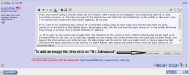
Posting pictures is pretty easy. I have attached a pictorial procedure. Just make sure they aren't too huge. I usually copy and paste mine into MS Paint, first, and make whatever notations I need, and crop and re-size them if needed, and then save them as JPG or PNG files. Try not to leave them as BMP (bitmap) files, since those usually have MUCH larger file sizes, compared to the compressed formats like JPG and PNG.
If you want to try something else, instead of re-doing the primary wiring at least make sure that the wire from the input connector to the switch is held tightly against the primary wires, ALL the way from the input connector to the switch. If it's not long-enough to do that, then it should probably be replaced.
i.e. If you just ran the switch wire straight from rear connector to the switch in front, without following the primary right up to the transformer on the way, so it could stay against the one primary wire while between the rear panel and the transformer, and against the other primary wire while between the transformer and the switch, then you might want to consider replacing that wire (from the input connector to the switch), so that it follows right against the primary wires, from the input connector, to the transformer, then to the switch.
While you're doing that, you "could" disconnect the primary wires and do the twisting. But (oops!) the primary wires are probably too short to do that, now. So I would probably just wrap the new input-connector-to-switch wire around the primary wires and see what happens.
Of course, if the wire from the connector to the switch IS still long-enough, then the first thing I might try might be zip-ties, to hold it right against the primary wires, everywhere. Or, disconnect one end and wrap it around the primaries as best you can, and then re-connect.
Posting pictures is pretty easy. I have attached a pictorial procedure. Just make sure they aren't too huge. I usually copy and paste mine into MS Paint, first, and make whatever notations I need, and crop and re-size them if needed, and then save them as JPG or PNG files. Try not to leave them as BMP (bitmap) files, since those usually have MUCH larger file sizes, compared to the compressed formats like JPG and PNG.
Attachments


Last edited:
- Status
- This old topic is closed. If you want to reopen this topic, contact a moderator using the "Report Post" button.
- Home
- More Vendors...
- Tubelab
- SSE - A question about hum.