If you are willing to pay a little more and wait for delivery from China I found some nice ceramic ones with gold pins on eBay. 1pc 4pin Gold Ceramic Vacuum Tube Valve Socket for 300B 2A3 801 274A Audio Amps | eBay.
I made a lower offer and they accepted.
Them do look nice much nicer than the ones I have already bought. I actually have bought two pair and I have already installed a pair on the board. I am waiting on the PS transformer before I can finish the amp. Thanks though and if I have any problem with the sockets I have installed I will give these some consideration.
I finished my 300B build this week with a couple of hiccups but all is well now. The amp sounds fantastic. How much better than the SSE is to be seen. I built the SSE a couple of months ago and it is a great amp as well using EL34 tubes. I will listen to the SE for a week or so to get use to it and then put the SSE back on the speakers for comparison.
One thing that is very obvious is that the SE is a much hotter running amplifier.
One thing that is very obvious is that the SE is a much hotter running amplifier.
Tubelab SE woes
I started the build of my Tubelab SE last fall. It didn’t take long for me to assemble the board. I set it up so I could put a motor run capacitor in parallel with C5 and I put a choke in place of R4.
Here are the major components:
Hammond 376XP transformer: 640V C.T. @ 173ma, 5V C.T. @ 3A and 6.3V C.T. @ 5A
James Audio Choke JS 5-200C: 5H 200ma
James Audio JS-6123HS output transformer x2 using the 5k tap.
Temco Motor Run Capacitor 100 uF 440 v
R14 and R15 are at 36kOhm
1N4007 diode in parallel with R30
Tube Complement Initial:
Electroharmonix 300B
Raytheon 5842
Sovtek 5AR4
I then needed a cabinet to support the transformers. I was fortunate to stop by Woodcrafters and get some Bubinga at half price. I spent the rest of the fall and winter assembling and getting the top of the cabinet routed. With the roughed out case and I connected the finished board and wired up all the transformers temporarily to check everything out.
Somewhere around 80% of my Variac I hit over 400V with no tubes so I did a quick switch and put in a 10uF cap at C4 to bound myself and be on the safe side. With that in place I got to 420V unloaded. I followed the checkout and got the tubes biased at about 65mA and around 350V (can’t find my notes). Then I ran into my overheating current regulator. A few heatsinks later I could crank up the voltage and play music though some ancient disposable front surrounds using a variable input from my Harmon Kardon CD player. It sounded ok, so I moved to my 95dB/m sacrificial Cerwin Vegas and it had plenty of volume. I then hooked it up to a pair of Cain & Cain Super Abbys and it sounded excellent.
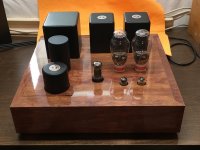
I took everything apart to finish the cabinet. Several months of spare time, drilling, sanding, coats of poly, sanding, polishing, sanding, coats of poly, over sanding, more coats of poly, sanding, polishing, sanding, more coats of poly. I finally got the case to a nice glossy finish – way too much work. Next time a satin finish.
While waiting for layers of polyurethane to cure, I decided I wanted a more B+ so I increased C4 to 22uf. I also added a 0.01uF 1kV ceramic disk capacitor between hot and neutral line inputs to remove any potential power switch noise.
With the cabinet done and the updates to my board I was ready to start the checkout procedure before soldering the transformer connections to the board. (I was using some temporary wiring and terminal strips for easy disassembly)
My B+ was up to 440V with my variac at about 100% and no tubes. I thought that would be ok once I loaded it down with tubes. I was wrong. It was still at 430V with the 5842s in place and their plate voltages at about 170V. I plugged in the 300Bs and only got to about 90% before I hit 400V. I was biasing the tubes as I cranked up the input voltage. The bias was around 70mA.
After several trials I finally got B+ down to about 360V with all tubes in place using 1.5uf film capacitor for C4. 5842s were at 175V and 300B bias was at about 70mA
I’m pretty sure the amp is now not nearly as loud and will not push the Cerwin Vegas very loud without distorting – nowhere near 95dB. The other thing I thought I noticed was that the bias was pretty constant when I first hooked it up several months ago, whereas currently I see the bias moving tens of milliamps to the music. When I turn the input down the bias stabilizes. I hooked up my old SSE amp and it drove the Cerwin Vegas loud with no issues. I also ran both amps with a preamp and got similar results.
Now I’m on to troubleshooting, but it is not my forte. I’m just a hobbyist with some aptitude, but no electrical design training. So I’ve been reading through some of the blogs and right now I’m thinking it might be in the semiconductor pairs.
Any help would be appreciated!
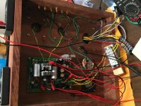
I attached a photo of the finished amp and one of the underside.
I started the build of my Tubelab SE last fall. It didn’t take long for me to assemble the board. I set it up so I could put a motor run capacitor in parallel with C5 and I put a choke in place of R4.
Here are the major components:
Hammond 376XP transformer: 640V C.T. @ 173ma, 5V C.T. @ 3A and 6.3V C.T. @ 5A
James Audio Choke JS 5-200C: 5H 200ma
James Audio JS-6123HS output transformer x2 using the 5k tap.
Temco Motor Run Capacitor 100 uF 440 v
R14 and R15 are at 36kOhm
1N4007 diode in parallel with R30
Tube Complement Initial:
Electroharmonix 300B
Raytheon 5842
Sovtek 5AR4
I then needed a cabinet to support the transformers. I was fortunate to stop by Woodcrafters and get some Bubinga at half price. I spent the rest of the fall and winter assembling and getting the top of the cabinet routed. With the roughed out case and I connected the finished board and wired up all the transformers temporarily to check everything out.
Somewhere around 80% of my Variac I hit over 400V with no tubes so I did a quick switch and put in a 10uF cap at C4 to bound myself and be on the safe side. With that in place I got to 420V unloaded. I followed the checkout and got the tubes biased at about 65mA and around 350V (can’t find my notes). Then I ran into my overheating current regulator. A few heatsinks later I could crank up the voltage and play music though some ancient disposable front surrounds using a variable input from my Harmon Kardon CD player. It sounded ok, so I moved to my 95dB/m sacrificial Cerwin Vegas and it had plenty of volume. I then hooked it up to a pair of Cain & Cain Super Abbys and it sounded excellent.
I took everything apart to finish the cabinet. Several months of spare time, drilling, sanding, coats of poly, sanding, polishing, sanding, coats of poly, over sanding, more coats of poly, sanding, polishing, sanding, more coats of poly. I finally got the case to a nice glossy finish – way too much work. Next time a satin finish.
While waiting for layers of polyurethane to cure, I decided I wanted a more B+ so I increased C4 to 22uf. I also added a 0.01uF 1kV ceramic disk capacitor between hot and neutral line inputs to remove any potential power switch noise.
With the cabinet done and the updates to my board I was ready to start the checkout procedure before soldering the transformer connections to the board. (I was using some temporary wiring and terminal strips for easy disassembly)
My B+ was up to 440V with my variac at about 100% and no tubes. I thought that would be ok once I loaded it down with tubes. I was wrong. It was still at 430V with the 5842s in place and their plate voltages at about 170V. I plugged in the 300Bs and only got to about 90% before I hit 400V. I was biasing the tubes as I cranked up the input voltage. The bias was around 70mA.
After several trials I finally got B+ down to about 360V with all tubes in place using 1.5uf film capacitor for C4. 5842s were at 175V and 300B bias was at about 70mA
I’m pretty sure the amp is now not nearly as loud and will not push the Cerwin Vegas very loud without distorting – nowhere near 95dB. The other thing I thought I noticed was that the bias was pretty constant when I first hooked it up several months ago, whereas currently I see the bias moving tens of milliamps to the music. When I turn the input down the bias stabilizes. I hooked up my old SSE amp and it drove the Cerwin Vegas loud with no issues. I also ran both amps with a preamp and got similar results.
Now I’m on to troubleshooting, but it is not my forte. I’m just a hobbyist with some aptitude, but no electrical design training. So I’ve been reading through some of the blogs and right now I’m thinking it might be in the semiconductor pairs.
Any help would be appreciated!
I attached a photo of the finished amp and one of the underside.
Attachments
That does look like a very nice finish. I was looking for that type finish on a guitar I built from a kit and got a high gloss finish like using Nitrocellulose lacquer. It's not as durable as polyurethane but is more forgiving in the application stage because rather than curing in layers which is what poly does when laquer is applied the solvent from the last coat dissolves the previous coat and the become one single coating. The finish is never smooth and perfect until you final sand and buff it out with polishing compound.
The bias is taken from the raw B+ if I am not mistaken. I found the two voltages to be so intertwined that to solve the issues I have with them I provided separate transformers for each. That worked fine. It requires changing where you input the B+ and how you use the board. It would take some fussing and I'm not sure you have the space for it now...
I was given good advice before I went thusly "off the reservation": go back to the original values and build to spec. This is advice I could not take but maybe you can")
Cheers!
I was given good advice before I went thusly "off the reservation": go back to the original values and build to spec. This is advice I could not take but maybe you can
Cheers!
.....
I’m pretty sure the amp is now not nearly as loud and will not push the Cerwin Vegas very loud without distorting – nowhere near 95dB. ....
The 5842 / 417A is prone to oscillation in my limited experience. If it went from working in a temp installation to non working after being placed in a permanent installation, I would at least consider this. I have found certain combinations of input cabling, volume control values and installation, and source characteristics to cause oscillation in my TSE builds. Working through this has been tedious trial and error to make mine stable. There is also an uprated spec for the input grid resistor.
.....
The other thing I thought I noticed was that the bias was pretty constant when I first hooked it up several months ago, whereas currently I see the bias moving tens of milliamps to the music. When I turn the input down the bias stabilizes. .....
Never observed this, so can't comment on whether or not an oscillating front end can produce this artifact. When I have blown a CCS or a MOSFET, the side with the blown component will go completely dead as far as output. So, it doesn't sound like a semiconductor problem to me.
edit: I also see you have audiophile type coupling capacitors. Those would be real high on my supect list. You might want to sub a plain vanilla cap in and see if your problems go away. Those ones you have could be leaky.
Win W5AJG
Last edited:
Enclosure Finish
Thanks! I should have put more effort into getting flat surfaces at the start and I think that would have saved me several poly coats and rounds of sanding. I used water based Rustoleum Ulitmate Polyurethane gloss finish.
That does look like a very nice finish. I was looking for that type finish on a guitar I built from a kit and got a high gloss finish like using Nitrocellulose lacquer. It's not as durable as polyurethane but is more forgiving in the application stage because rather than curing in layers which is what poly does when laquer is applied the solvent from the last coat dissolves the previous coat and the become one single coating. The finish is never smooth and perfect until you final sand and buff it out with polishing compound.
Gorgeous finish on that enclosure, you can tell you put a lot of effort into it
Thanks! I should have put more effort into getting flat surfaces at the start and I think that would have saved me several poly coats and rounds of sanding. I used water based Rustoleum Ulitmate Polyurethane gloss finish.
Tubelab SE Troubleshooting.
Thanks for the guidance! I'll take a look at my input grid resistors, the coupling caps and maybe swap out the 5842s for some RCAs I picked up. I'm also glad to know I don't need to start with the CCS or MOSFETs. I'll also see what I can do to get closer to the "reservation"
The bias is taken from the raw B+ if I am not mistaken. I found the two voltages to be so intertwined that to solve the issues I have with them I provided separate transformers for each. That worked fine. It requires changing where you input the B+ and how you use the board. It would take some fussing and I'm not sure you have the space for it now...
I was given good advice before I went thusly "off the reservation": go back to the original values and build to spec. This is advice I could not take but maybe you can
Cheers!
The 5842 / 417A is prone to oscillation in my limited experience. If it went from working in a temp installation to non working after being placed in a permanent installation, I would at least consider this. I have found certain combinations of input cabling, volume control values and installation, and source characteristics to cause oscillation in my TSE builds. Working through this has been tedious trial and error to make mine stable. There is also an uprated spec for the input grid resistor.
Never observed this, so can't comment on whether or not an oscillating front end can produce this artifact. When I have blown a CCS or a MOSFET, the side with the blown component will go completely dead as far as output. So, it doesn't sound like a semiconductor problem to me.
edit: I also see you have audiophile type coupling capacitors. Those would be real high on my supect list. You might want to sub a plain vanilla cap in and see if your problems go away. Those ones you have could be leaky.
Win W5AJG
Thanks for the guidance! I'll take a look at my input grid resistors, the coupling caps and maybe swap out the 5842s for some RCAs I picked up. I'm also glad to know I don't need to start with the CCS or MOSFETs. I'll also see what I can do to get closer to the "reservation"
Cool 300B SE?
After reading various accounts on the Forum I’m thinking of a building a lower powered 300B SE and would be shooting for a B+ of around 350. I’m looking to avoid some of the overheating problems that others have faced.
Would a 600 volt PT be right choice for this?
I’m looking at the Weber wpt30 and the Hammond 272FX
The Weber looks interesting, but it provides 250ma at 560 or 600 volts, 5v at 3amps, and 6.3 volts at 7 amps. I understand I won’t need all that current, but does the extra-unused power create more heat or is it just there in reserve?
The Hammond specs 600 v at 172ma, 5v at 3 amps and 6.3 at 5 amps.
Which option would create less heat? Which is more compatible with the standard parts listed on the Tubelab site?
I’m planning on using Transcender OT’s, I’m leaning toward the 3.5 to 8 ohm in the 15 watt size.
My Monitor Audio speakers are 91db and currently sound great with my SSE.
Thanks for your help, Jacques
- Status
- This old topic is closed. If you want to reopen this topic, contact a moderator using the "Report Post" button.
- Home
- More Vendors...
- Tubelab
- Tubelab SE