Hi there,
I am about to start assembly of a Tubelab SE board and I am wondering how critical it is that the tube sockets are soldered directly onto the PCB.
The reason for the question is that I'd like to put it in a chassis such that the tube sockets are flush with the top.
Not having deep theoretical knowledge, I still suspect that the signal paths should probably stay as short as possible, but I wonder what the effects are if I would solder extensions onto the board to raise the sockets enough to clear the large electrolytics.
I figure I'd only need about an inch or so.
Any advice/experience if that would have noticeable negative impact on sound quality or other characteristics?
Thanks for your thoughts!
Stefan
Why not mount the components on the bottom?
Thanks Nic.
Yeah, thought about that, too. That's what I did in my Simple SE.
It seems more opportunity to screw it up on the SE due to more silicon...

I also had a hard time getting the aluminum top plate for my chassis punched exactly right for the four tube sockets. Having a little more wiggle-room would be helpful. Or just bigger holes.....
I am probably going to do the bottom mount for the tall stuff again, I was just mainly curious to see if extending the sockets off and hence adding track/wire length will have significant undesirable side effects.
Cheers,
Stefan
Hi Stefan,
All I can say is that sometimes this matters, and some times it doesn't.
If you can build it per the instructions or examples, you are pretty much assured it will work as it was intended. Once you start deviating, you're on your own. I wouldn't extend the connections to any tubes (except rectifiers and "magic eye" tubes) if I were you. This is especially true if you don't have much knowledge and equipment for troubleshooting.
Hi Green77,
-Chris
All I can say is that sometimes this matters, and some times it doesn't.
If you can build it per the instructions or examples, you are pretty much assured it will work as it was intended. Once you start deviating, you're on your own. I wouldn't extend the connections to any tubes (except rectifiers and "magic eye" tubes) if I were you. This is especially true if you don't have much knowledge and equipment for troubleshooting.
Hi Green77,
That's an awful long way from saying it works properly. It may be doing some things that you are unaware of. Possibly, if i was built properly you may hear that you had problems before. No one can be sure without doing some actual stuff with test equipment. Believe me, I've seen over 35 years off misbehaving equipment where the owner was sure everything was fine. The next comment goes something like this ... "I can't believe I didn't hear a problem for so long, but it's much better now." Life in an audio service shop.... sound was perfect!!
-Chris
Hi Green77,
Well, that's all fine and dandy. The problem as I see it is that your advice to another person isn't based in fact at all. Certainly not in very good odds of success. His build is not familiar to you as far as the layout, so advice like that is not responsible I feel.
I'll assume you checked your wave forms with a 'scope, decent sine wave source and THD analyzer a the very least - right? That is the only way you could possibly confirm that the circuit is in fact operating properly. Just listening really doesn't cut it, although with some practice, trained listening may be able to detect a fault. This does not normally work in my experience with many, many other people.
In the high end audio servicing business, I often had people come in for some "improvement" to their equipment that they've heard or read somewhere. It became much more common place once the internet became popular. In almost all cases, the equipment had problems with it's performance even though the customers indicated that there were no other issues to be concerned about. As is customary, the equipment is tested and some measurements made in a case like this. This is so we can ensure the equipment is not suffering any performance issues, and to also make a performance reference to refer back to. My deal with people in this situation has always been, "let's get this thing running properly before we begin changing things". The idea is to have them hear the equipment working properly at home before messing with it further. In every case the customer has been shocked to find out that the equipment has not been performing well at all for years. They usually are happy enough to leave it alone, depending on the modification. There are times that I'll perform a change for improvement because it will make a positive improvement in performance. Something that follows the guidelines for improving linearity (a real modification). Since I now have performance figures before, after repairing and after changes, I can justify the work for the customer. Things like these are typically discussed beforehand.
Sorry, a technician's viewpoint that is supported by many years of direct experience with audio equipment. Listening for problems normally will only find problems that have already become serious performance problems. BTW, I listen as well as measure. Both methods must agree that changes are in fact positive ones.
-Chris
The 5842s like to oscillate. It's important that the grid stopper is on the tube socket instead of on the PCB if you move the socket off the board. I would do the same to the grid stopper on the output tube, but it is less critical. The output tubes on my TSE are off the board while the input tubes are standing on "socket savers" to get the clearance that I need.
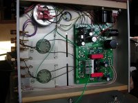
I originally built the PCB with the tall components on the bottom. The heat sinks need to be rotated, which gets a little tricky because these are soldered to the PCB (unlike the SSE). When you do this, they hover over the solder pad of 1 or 2 resistors, so you have to stand-off the heat sink or file a notch into it. The filament regulator is another tricky bit. It can't be mounted to the bottom because it has 4 pins, not 3. I opted to flatten the leads and hang it off the end. This will require a bit of fabrication for a heat sink. Here are some pictures, if you are curious:
Tubelab SE – Pictures – metaruss
The 5842s like to oscillate. It's important that the grid stopper is on the tube socket instead of on the PCB if you move the socket off the board. I would do the same to the grid stopper on the output tube, but it is less critical. The output tubes on my TSE are off the board while the input tubes are standing on "socket savers" to get the clearance that I need.
I originally built the PCB with the tall components on the bottom. The heat sinks need to be rotated, which gets a little tricky because these are soldered to the PCB (unlike the SSE). When you do this, they hover over the solder pad of 1 or 2 resistors, so you have to stand-off the heat sink or file a notch into it. The filament regulator is another tricky bit. It can't be mounted to the bottom because it has 4 pins, not 3. I opted to flatten the leads and hang it off the end. This will require a bit of fabrication for a heat sink. Here are some pictures, if you are curious:
Tubelab SE – Pictures – metaruss
Thanks Russ, very helpful!
I think I may put the silicone that will cause mechanical issues when bottom mounted on a little satellite board that will mount to a sizeable heat-sink and run short wires to the solder pad. Those connections should be less critical in terms of wire length as long as I keep them as short as possible. I'll play around with it once I get started; still waiting for parts.
I'll let y'all know how it goes!
Cheers,
Stefan
The gate of the MOSFETs might need to have their gate stoppers moved close to the FET lead as well. They can oscillate too.
Those look to be fine mounted on the bottom, if I can get them on the other side of the heat sink without the Q2/Q2 U2/U3 heatsinks colliding.
We'll see, thanks for the hint, I didn't know about the oscillation risk for the MOSFETs!
The reason for the question is that I'd like to put it in a chassis such that the tube sockets are flush with the top.
Thanks for your thoughts!
Stefan
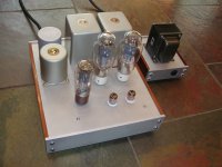
I built my Tubelab SE with the sockets flush with the top, and they are soldered directly to the PCB..........the PCB is hanging from the top deck with threaded standoffs. Everything except the tube sockets is mounted on the bottom of the PCB. The only thing that's a bit tricky is the filament regulator; just bend the leads and triple-check.
If your punched holes are a little off, you can still do this technique with slightly oversized chassis holes. When making them oversized, you have another chance to get them lined up properly, and the extra clearance will help with ventilation. My sockets fit quite snug so I added a couple of vent slots reasonably near the heat sinks. The amp has been working fine for months, no overheating of the regulator with 300B's.
Attachments
Some builders have had success mounting the tube sockets off board, others have built radio and TV jammers. The 5842 / mosfet combination will oscillate if given a tiny chance. I would put the grid stopper right at the grid pin of the 5842 socket.
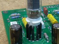
I have sometimes made socket extensions using brass tubing from a hobby shop to elevate the socket above the PC board. The tubing is covered with heat shrink tubing in this photo.
I have sometimes made socket extensions using brass tubing from a hobby shop to elevate the socket above the PC board. The tubing is covered with heat shrink tubing in this photo.
Attachments
<...> others have built radio and TV jammers.<..>
I have been convinced. I will go with on-top sockets, on-back components and make the rest fit using the tips you all gave me.
THANK YOU!
- Status
- This old topic is closed. If you want to reopen this topic, contact a moderator using the "Report Post" button.
- Home
- More Vendors...
- Tubelab
- Tubelab SE - Sockets off PCB?