Lowering B+
Hi Russ,
I was really targeting a B+ between 425v - 450v, but I guess that is up to the H.V. transformer. I am using the Allied transformer that George mentions on the website. I actually have several different resistor values ranging from 560 ohms all the way up to 1k ohm. As I stated before, I was targeting 45ma because of the output transformers I will eventually use. I do believe if I had the B+ I was targeting, the operating point would be exactly right for a 6L6 tube. I will put a tube rectifier in, but Russ, is there an additional way to lower the B+ by 20v or so ?? I am worried that the high B+ might shorten tube life?? Ty, that checkout you put together is awesome!!! It was easy to follow and definitely a must for any newbie. I did some more listening and the amp is dead quiet!!!! The only noise I can hear when my ear is up to the speaker , is from my preamp which has a very,very,very low hum(I ave been chasing this for months
  ). But sonically, the amp is amazing and I can't believe how loud it plays, currently I am using my small (backup) bookshelf speakers, I believe they are in the 87 - 88db sensitivity range. Once I have playing time, I will move to my large bookshelf speakers which are a little more sensitive, but go much deeper in bass response!
Regards
Hi Russ,
I was really targeting a B+ between 425v - 450v, but I guess that is up to the H.V. transformer. I am using the Allied transformer that George mentions on the website. I actually have several different resistor values ranging from 560 ohms all the way up to 1k ohm. As I stated before, I was targeting 45ma because of the output transformers I will eventually use. I do believe if I had the B+ I was targeting, the operating point would be exactly right for a 6L6 tube. I will put a tube rectifier in, but Russ, is there an additional way to lower the B+ by 20v or so ?? I am worried that the high B+ might shorten tube life?? Ty, that checkout you put together is awesome!!! It was easy to follow and definitely a must for any newbie. I did some more listening and the amp is dead quiet!!!! The only noise I can hear when my ear is up to the speaker
, is from my preamp which has a very,very,very low hum(I ave been chasing this for months ). But sonically, the amp is amazing and I can't believe how loud it plays, currently I am using my small (backup) bookshelf speakers, I believe they are in the 87 - 88db sensitivity range. Once I have playing time, I will move to my large bookshelf speakers which are a little more sensitive, but go much deeper in bass response!Regards
New ouput transformers
Hi,
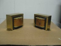
New output transformers finally arrived and can't wait to hear them. I have put over 100 hours on both EL34 and 6L6GC tubes, each imparts there own magic!! The more I listen to this amp the more amazed I am at the sound for a DIY project, great job George!! I have a lot of listening time with the Trancendar transformers(still available on eBay!) and I can say the sound is lacking for nothing, from top to bottom it is A+++++ I agree with George, the sound you get will largely depend on the quality of the output transformers!! I am really curious about what sound I will get now, these transformers took about 5 weeks to get. I have posted a picture and will comment on sound after I get some playing time. I get way more volume then I need, I am using a preamp (DIY tube, ), 2 turntables for source ( one MM one MC ), and large bookshelf(?) type speakers. I believe my speakers are rated at about 88-90db efficiency?? I never get past half volume on the preamp, lower with the MC cartridge due to additional gain of the phono stage.
Regards
PS I forgot the new transformers are Magnequest RH-60 ( Robin Hood series, everything else was out of my budget!!!)
Hi,
New output transformers finally arrived and can't wait to hear them. I have put over 100 hours on both EL34 and 6L6GC tubes, each imparts there own magic!! The more I listen to this amp the more amazed I am at the sound for a DIY project, great job George!! I have a lot of listening time with the Trancendar transformers(still available on eBay!) and I can say the sound is lacking for nothing, from top to bottom it is A+++++ I agree with George, the sound you get will largely depend on the quality of the output transformers!! I am really curious about what sound I will get now, these transformers took about 5 weeks to get
. I have posted a picture and will comment on sound after I get some playing time. I get way more volume then I need, I am using a preamp (DIY tube, ), 2 turntables for source ( one MM one MC ), and large bookshelf(?) type speakers. I believe my speakers are rated at about 88-90db efficiency?? I never get past half volume on the preamp, lower with the MC cartridge due to additional gain of the phono stage.Regards
PS I forgot the new transformers are Magnequest RH-60 ( Robin Hood series, everything else was out of my budget!!!)
Attachments
Lower B+ Voltage
Hi Russ,
I finally got the 5AR4 rectifier tube and have placed it in the amp and removed the jumper for the diode rectifier. I am now observing a B+ between 450v and 460v on the 2 resistors. The question I have is that the B+ seems to be about 2 1/2% higher on one side. Other than that, the amp sounds amazing and I am loving it more and more. The more I listen to it, the more amazed I am that I actually built it . It really can put some well known and expensive commercial units to shame, get has done an amazing job with this amplifier. I am now trying to decide on the chassis so I can finish it off. The new output transfomers have taken the sound to a whole new level!
Regards
Hi Russ,
I finally got the 5AR4 rectifier tube and have placed it in the amp and removed the jumper for the diode rectifier. I am now observing a B+ between 450v and 460v on the 2 resistors. The question I have is that the B+ seems to be about 2 1/2% higher on one side
. Other than that, the amp sounds amazing and I am loving it more and more. The more I listen to it, the more amazed I am that I actually built it . It really can put some well known and expensive commercial units to shame, get has done an amazing job with this amplifier. I am now trying to decide on the chassis so I can finish it off. The new output transfomers have taken the sound to a whole new level!Regards
Glad to hear you are happy. Which resistors are you referring to? Where are you doing the measurement and getting the difference between the two sides?
If you are measuring around the input tube plate (R14, etc), then you may see a difference just because of the tolerances of the resistors you are measuring across. The CCS is setup by R13/23, which is a precision resistor and should set the plate currents very close to each other. R14/24 are 5% resistors, so the voltage across them may be different even though the currents are the same.
If you are talking about the output tube cathodes, then you are mainly seeing the difference between the two tubes. They are not very closely matched at this operating point.
B+ Voltage
Hi Russ,
Yes I was talking about R14 and R24, sorry I did not include that in my post. Is there any other way to reduce the B+ voltage. Although I am at the voltage I was shooting for ( 450v B+ ), it does seem to drift about 20 v sometimes, I am assuming that could be because of increases in line voltage. Yes, I am very happy with the amp, I cannot believe how loud 4 or 5 watts can be.
Regards
Hi Russ,
Yes I was talking about R14 and R24, sorry I did not include that in my post. Is there any other way to reduce the B+ voltage
. Although I am at the voltage I was shooting for ( 450v B+ ), it does seem to drift about 20 v sometimes, I am assuming that could be because of increases in line voltage. Yes, I am very happy with the amp, I cannot believe how loud 4 or 5 watts can be.Regards
The drift is probably due to the line voltage, yes. Are you using any inrush limiters?
Increasing the amount of R in the power supply would decrease B+ at the expense of more heat and less regulation (the latter not being too important for an SE amp). The simplest way is to add some series resistance before the choke.
The other option is to reduce the size of C1. This will make the choke do more of the energy storage (like a choke-input filter). This value to use is most easily determined using PSUD, though something like 10uF is usually required. This may increase ripple by about 5x or so, depending how much C2 your have and how big your supplemental capacitor is. The other wrinkle here is that you won't find a snap-in cap that will fit perfectly in the C1 position smaller than 33uF, which is not low enough. A regular, leaded cap will fit if it is dangled a bit to match the lead spacing.
B+ Voltage
Hi Russ,
My C1 is currently 33uf and C2 is 220uf. The supplemental cap is 50uf. If I am understanding your reply; by lowering the value of C2, I would lower the B+ at the expense of higher ripple(noise) on the B+. I could use a Motor run type capacitor of 10uf value in place of current C1, that would drop more voltage across the choke??
Regards
Hi Russ,
My C1 is currently 33uf and C2 is 220uf. The supplemental cap is 50uf. If I am understanding your reply; by lowering the value of C2, I would lower the B+ at the expense of higher ripple(noise) on the B+
. I could use a Motor run type capacitor of 10uf value in place of current C1, that would drop more voltage across the choke??Regards
If I am understanding your reply; by lowering the value of C2, I would lower the B+ at the expense of higher ripple(noise) on the B+
Lowering C1 will, yes. Don't lower C2...that will just increase ripple. Sounds like you already upgraded C2 to 220uF and also have the extra 50uF. I wouldn't worry about ripple then...you will only have about 100mV or so with 10uF C1.
I suggest you grab PSUD and see what I mean. It's not hard to use once you get the hang of it and it lets you fiddle with various values as much as you want to see what happens. Since you already have the power transformer (to measure the secondary DCR) and a working version of the supply, you can tweak the simulation to get very accurate results.
Attached is a PSU file to get you started, based on what I know about the components you are using.
You'll want to measure the AC voltage of your transformer HV secondary without a load (remove the rectifier). Also measure the DC resistance of it (unpowered, of course). Divide the voltage you got by 2 and enter it and the resistance into the simulation (double-click on the value in the diagram). Run the simulation for 2000ms. Then click the "V(C2)" check box in the list to graph the result and see how close it gets to what you measure on C2 in your amp.
You'll want to measure the AC voltage of your transformer HV secondary without a load (remove the rectifier). Also measure the DC resistance of it (unpowered, of course). Divide the voltage you got by 2 and enter it and the resistance into the simulation (double-click on the value in the diagram). Run the simulation for 2000ms. Then click the "V(C2)" check box in the list to graph the result and see how close it gets to what you measure on C2 in your amp.
Attachments
Last edited:
- Status
- This old topic is closed. If you want to reopen this topic, contact a moderator using the "Report Post" button.
- Home
- More Vendors...
- Tubelab
- Simple SE power transfomer question?