Started my TSE a few years ago, but it was set aside, but resurrected the project in the beginning of the year.
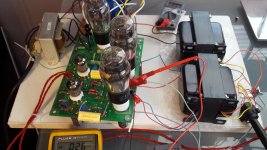
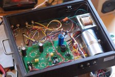
Got it working this weekend, pic shows it setup on a board to make sure it all works.
45 Headphone amp using Electra print low IMD iron, 5k@50ma with 46 and 300 ohm secondary taps.
Edcor power tx in the back. 5V4 rectifier and I think they were amphenol 5842 driver tubes. Have a pair of we 417a's that I'll put in later, after I box it up.
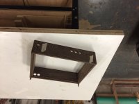
Making a wooden chassis for it that's 90% done. Need to finish the box so I can move it to its permanent home.
But in the meantime I'm using it, and its making sweet music, I think I get the 45 tube love now.
One think is my B+ is a bit high because my line AC also runs on the high side, around 120-122VAC, so B+ with 4.7u is about 337VAC. Would prefer a little lower, but 45's are working fine.
I have a variac, so I can run B+ lower, but I don't want to use the variac on it forever.
Got it working this weekend, pic shows it setup on a board to make sure it all works.
45 Headphone amp using Electra print low IMD iron, 5k@50ma with 46 and 300 ohm secondary taps.
Edcor power tx in the back. 5V4 rectifier and I think they were amphenol 5842 driver tubes. Have a pair of we 417a's that I'll put in later, after I box it up.
Making a wooden chassis for it that's 90% done. Need to finish the box so I can move it to its permanent home.
But in the meantime I'm using it, and its making sweet music, I think I get the 45 tube love now.
One think is my B+ is a bit high because my line AC also runs on the high side, around 120-122VAC, so B+ with 4.7u is about 337VAC. Would prefer a little lower, but 45's are working fine.
I have a variac, so I can run B+ lower, but I don't want to use the variac on it forever.
Attachments
...
One think is my B+ is a bit high because my line AC also runs on the high side, around 120-122VAC, so B+ with 4.7u is about 337VAC. Would prefer a little lower, but 45's are working fine.
I have a variac, so I can run B+ lower, but I don't want to use the variac on it forever.
Change C4 to a smaller value? Buy some smaller sizes (20-10-5uF?) to test and clip-lead each one in to test.
Change C4 to a smaller value? Buy some smaller sizes (20-10-5uF?) to test and clip-lead each one in to test.
C4 was 4.7uf when I measured 337V B+.
I looked in my junk drawer last night, and found a 2uf oil filled cap. Tried that, lowered B+ by about 10V, but amp was distorting. Changed caps to a 3.3uf, which made B+ about 334V, but still had distortion.
Wondering if somehow the oil filled cap damaged my rectifier tube? Theres not much to damage in this amp, and I was only playing with the PS section.
Was depressed about it last night, but will try another rectifier tube and put the 2uf cap back in the junk drawer.
Randy
Looks like you have a CLC filter. You could eliminate the first capacitor and try LC filtering with a larger cap after the choke. This will give you maximum voltage reduction and could still be acceptable filtering. You can add as many chokes and capacitors as you want, possibly running LCLC with an additional C-14X.
This may be of interest to you - YouTube
The data sheet for your rectifier will show how much first-stage capacitor loading the rectifier will withstand. In theory it's the other direction (too much capacitance) that will damage rectifiers due to an overly large turn-on current surge, or excessive current ripple when operating. A smaller capcitor should be less demanding of current surges. Reactor current will rise slowly and smooth the current surge, which should be easier on the rectifier.
Last edited:
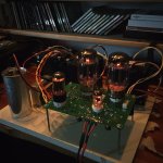
[FONT=Helvetica, sans-serif]My first amplifier I made back in 1964 used EF50 pre amp, 6SN7 pre driver, 807 phase splitter and 813 output valves. The mains transformer was hand built by me, as was the output transformer.[/FONT]
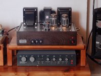
[FONT=Helvetica, sans-serif]In this build, I used a 6SL7 input stage using both sides for good gain followed by a 6SN7 pre-driver and balanced phase splitter. The latter drives a pair of 807 valves (that have similar characteristics to 6L6GC but work at a much higher voltage for more voltage swing and therefore better dynamic range and headroom) in Ultra Linear class AB1 configuration.[/FONT]
[FONT=Helvetica, sans-serif]The amplifier employs 18dB of negative feedback and has a frequency response of 20HZ - 20kHZ +- 1dB so pretty much covers everything the human ear can hear and feel.[/FONT]
[FONT=Helvetica, sans-serif]I have sold three that were made and over two years my clients have been extremely happy with them. I kept number four for myself.
[/FONT]
[FONT=Helvetica, sans-serif]The pre-amp is based on the Quad II and employs an EF86 RIAA stage and an ECC83 Baxandal tone control with +-16dB below 1kHZ and above.[/FONT]
[FONT=Helvetica, sans-serif]Valves produce a logarithmic sound curve and that suits the human ear unlike solid state linear amplifiers.[/FONT]
[FONT=Helvetica, sans-serif]It took 12months from concept to finished product for the amplifier and 8months for the pre amp.[/FONT]
[FONT=Helvetica, sans-serif]
[/FONT]
[FONT=Helvetica, sans-serif]The transformers and chassis are made in England. The valves are from the USSR and from a Valve Manufacturing Plant by Sovtec, Svetlana or Foton and have the Winged C logo on a few. The units were designed and assembled in Weymouth, UK me. I am competent design engineer with many years experience.[/FONT]
[FONT=Helvetica, sans-serif]
[/FONT]
[FONT=Helvetica, sans-serif]Spares are plentiful and reliable.[/FONT]
Attachments
Looks like you have a CLC filter. You could eliminate the first capacitor and try LC filtering with a larger cap after the choke. This will give you maximum voltage reduction and could still be acceptable filtering. You can add as many chokes and capacitors as you want, possibly running LCLC with an additional C-14X.
The data sheet for your rectifier will show how much first-stage capacitor loading the rectifier will withstand. In theory it's the other direction (too much capacitance) that will damage rectifiers due to an overly large turn-on current surge, or excessive current ripple when operating. A smaller capcitor should be less demanding of current surges. Reactor current will rise slowly and smooth the current surge, which should be easier on the rectifier.
I do have CLC, and was considering maybe a LCLC, but would have to buy another inductor. Then I found this thread yesterday,
Lowering B+ voltage
Seems if the inductor is first, need a bigger, beefier inductor.
I know making the cap smaller should not hurt the rectifier, but all I changed was the one cap after the rectifier from a 4.7uf film to a 2uf oil filled, and it caused distortion. The distortion remained when I changed to a 3.3uf film.
I'll probably switch back to the 4.7uf film first, and see if that fixes it. Otherwise I have other rectifiers I can try.
Randy
Didn't notice. I am English and 'tube' is not a word I use to describe valves. Threw me off the title a bit.^ Did you know that this thread is "Pictures of your Tubelab amp"?
Some nice amplifiers though to be seen on this thread.
Mmm. Isn't that a Triad C-14X? $15 from Mouser. C-14X Triad Magnetics | Mouser rated at 200 mA, should be planty. Maybe there's something different about choke input that I'm not appreciating ... I'll check the RDH later. The C-14X has 150 ohms which in itself will drop your voltag by ca 15....
Seems if the inductor is first, need a bigger, beefier inductor.
The change in B+ voltage will change the bias setting a bit. I wouldn't think it would be enough to make noticeable distortion, but maybe. You can use a really small film cap in that first position and still have a CLC ... that's demonstrated in the video I linked. If you have a coupling cap of the proper voltage, you could try that too. What's your rectifier, a 5V4G? Possible it's a coincidental failure.I know making the cap smaller should not hurt the rectifier, but all I changed was the one cap after the rectifier from a 4.7uf film to a 2uf oil filled, and it caused distortion. The distortion remained when I changed to a 3.3uf film.
I'll probably switch back to the 4.7uf film first, and see if that fixes it. Otherwise I have other rectifiers I can try.
Randy
Last edited:
I'm an idiot lol
Accidentally had switched the output tx switch, so I had the high impedance windings trying to drive low impedance cans. Flipped switch back, and distortion was gone.
Went back to 2uf cap, voltage around 325V now with 5V4 rectifier. The 5V4 seem to be a decent compromise between startup time and voltage. Not as slow as 5AR4, but lower voltage. Will see what 1 uf cap gives me.
Randy
Changed to 1uf and get just under 300V now.
Downside is I think I hear a little more hum, and psud does show the ripple goes up as I make this cap smaller.
800mv for 1uf
530mv for 2uf
223mv for 4.7uf
Looks like the answer is to add another LC stage as suggested, to make a CLCLC filter instead of the CLC that I have now. I think it should be pretty easy to install two inductors in series across R4, and then add a 100uf cap from ground to between the two inductors.
Adding another C-14X knocks the ripple down to 4mv, way less than I have now.
My final build will include a couple ASC oil filled caps, which should make even quieter.
Randy
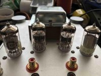
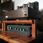
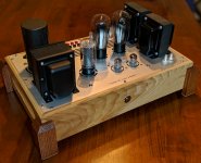
Here's my SSE running EH KT-88s and the Edcor transformers, and a NOS Mullard 12AT7.
A really fun build and just sounds sooo good. I'd done simpler kits like the S-5 K-12G, but this was the first sourcing the parts and making it.
I first got it running Fall '15, but still had to finish the chassis. *Finally* finished that Spring '17. Took a while... And then even longer to post pics.
Chassis is wenge with walnut splines, and an aluminum top. Switchcraft switches, and cabinet drawer handles on the sides to make it easy to lift. Motor run capacitor and choke are inside. Wiring is reasonably tidy. My previous woodworking business was called "Gowanus Furniture" so I put my tag on the left there, and sort of made it in the style of my Apt pre.
Many thanks to George for making it, and for patiently answering my noob questions here when I was building it!
Attachments
Last edited:

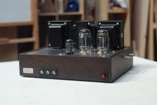
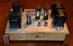
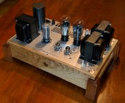
TSE 45
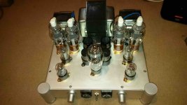
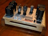
I was probably one of the last few to purchase a first gen TSE board from George before his supply ran out. This is my first tube amp build and it has been a rewarding experience, from the electrical build > to designing the top plate in AutoCAD > to my novice woodworking skills.
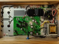
Many thanks to George and this great forum and those who post here. I had no issues during the checkout process and the build really went smoothly. All components (minus the power switch) are mounted to the top plate and the whole thing can be removed from the cabinet easily if needed. The amp sounds phenomenal and I couldn't ask for anything better!
Nothing out of the ordinary, but a few details:
Edcore XPWR131-120 power transformer
Triad C-14X choke
Electra Print 5K@50ma audio output transformers
Temco 100mfd motor run cap
5U4 rectifier
RCA UX-245 output tubes
Front Panel Express 10" x 16-1/2" brushed aluminum top plate
Flush-mounted tube sockets
Test points in top panel for easy access
Hickory cabinet finished with shellac with oak legs
The amp currently drives a pair Klipsch KG 5.5 speakers with plenty of power for my needs.
I was probably one of the last few to purchase a first gen TSE board from George before his supply ran out. This is my first tube amp build and it has been a rewarding experience, from the electrical build > to designing the top plate in AutoCAD > to my novice woodworking skills.
Many thanks to George and this great forum and those who post here. I had no issues during the checkout process and the build really went smoothly. All components (minus the power switch) are mounted to the top plate and the whole thing can be removed from the cabinet easily if needed. The amp sounds phenomenal and I couldn't ask for anything better!
Nothing out of the ordinary, but a few details:
Edcore XPWR131-120 power transformer
Triad C-14X choke
Electra Print 5K@50ma audio output transformers
Temco 100mfd motor run cap
5U4 rectifier
RCA UX-245 output tubes
Front Panel Express 10" x 16-1/2" brushed aluminum top plate
Flush-mounted tube sockets
Test points in top panel for easy access
Hickory cabinet finished with shellac with oak legs
The amp currently drives a pair Klipsch KG 5.5 speakers with plenty of power for my needs.
Attachments
-
 00100dPORTRAIT_00100_BURST20190509210733684_COVER (1).jpg633.5 KB · Views: 629
 -
 00100dPORTRAIT_00100_BURST20190509210800221_COVER.jpg454.8 KB · Views: 634
 -
 00100dPORTRAIT_00100_BURST20190509210822732_COVER.jpg496.2 KB · Views: 556
 -
 00100dPORTRAIT_00100_BURST20190509210935382_COVER (1).jpg553.5 KB · Views: 595
 -
 00000IMG_00000_BURST20190511125900433_COVER.jpg799.2 KB · Views: 680
You're too modest. Beautiful work all around! Lots of good ideas in there, not to mention that it's one of the more creative physical arrangements I've seen. Similar to moggi1964's amp in post 460 above (another gorgeous amp that I just now noticed), but with additional test points. Congratulations!Nothing out of the ordinary...
Last edited:
I was probably one of the last few to purchase a first gen TSE board from George before his supply ran out. This is my first tube amp build and it has been a rewarding experience, from the electrical build > to designing the top plate in AutoCAD > to my novice woodworking skills.
The top plate is really nice. Any chance you could share the file? I'm sure it was a lot of work, and it came out really nice. If I ever build another TSE, I'd like to use them as a starting point. I'll admit the chances are currently slim I'd make another TSE, but things change lol
BTW, for a novice, your woodworking is really nice.
Randy
Guys, thanks for the kind words. PM me if you want the file, but keep in mind this layout only works with the original (and now-obsolete) TSE boards due to the different tube spacing on George's new boards.
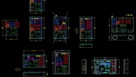
I played with several top plate designs in AutoCAD while aiming for the smallest footprint (without placing tubes right up against transformers). I finally settled on the version in the lower right corner in the attached screenshot. The heatsink that I pulled from my junk box also played a big part in the layout as well as designing in (future proofing?) some alternate cooling options if needed later down the road.
Yes, randytsuch, lots of great builds and ideas on this forum to pull from!
Attachments
Here's my SSE running EH KT-88s and the Edcor transformers, and a NOS Mullard 12AT7.
A really fun build and just sounds sooo good. I'd done simpler kits like the S-5 K-12G, but this was the first sourcing the parts and making it.
I first got it running Fall '15, but still had to finish the chassis. *Finally* finished that Spring '17. Took a while... And then even longer to post pics.
Chassis is wenge with walnut splines, and an aluminum top. Switchcraft switches, and cabinet drawer handles on the sides to make it easy to lift. Motor run capacitor and choke are inside. Wiring is reasonably tidy. My previous woodworking business was called "Gowanus Furniture" so I put my tag on the left there, and sort of made it in the style of my Apt pre.
Many thanks to George for making it, and for patiently answering my noob questions here when I was building it!
Beautiful
- Home
- More Vendors...
- Tubelab
- Pictures of your Tubelab amp