spp help
I need help with my spp Im not a total novice Ive made at least 10 guitar amps ranging from marshalla to fenders to matchless all point to point made my own turret boards , this is my first stereo with a pcb thought it would be pretty straight forward but I cant seem to get it sorted I can just hear a signal if I put my ear to the speaker Ive Pulled the board checked all components my voltages seem okay its doing my head in.Ive traced a signal all the way thru to the primary out but when it comes back from the output tranny secondary its quieter than going in
I need help with my spp Im not a total novice Ive made at least 10 guitar amps ranging from marshalla to fenders to matchless all point to point made my own turret boards , this is my first stereo with a pcb thought it would be pretty straight forward but I cant seem to get it sorted I can just hear a signal if I put my ear to the speaker Ive Pulled the board checked all components my voltages seem okay its doing my head in.Ive traced a signal all the way thru to the primary out but when it comes back from the output tranny secondary its quieter than going in
Properly punctuated English translation: (This is what happens when I wake up at 4:00 AM, read the online newspaper and check DIY Audio afterwards. I read your post and thought it was because I'm groggy and haven't had my coffee. Promise though, starting tonight, I'll try and stay up later so I don't wake up so early. Thought to myself, self, with this translation, maybe someone on the forum can help this person out.)
I need help with my SPP. I'm not a total novice, I've made at least 10 guitar amps ranging from Marshall to Fender's to Matchless- all point to point. I also made my own turret boards. This is my first stereo with a PCB. Thought it would be pretty straight forward, but I can't seem to get it sorted.
I can just hear a signal if I put my ear to the speaker. I've pulled the board, checked all components. My voltages seem okay. It's doing my head in. I've traced a signal all the way thru to the primary out, but when it comes back from the output tranny secondary, it's quieter than going in.
(I'm also not sure what a output tranny secondary is? Do you mean the signal from the anode to the input of the output transformer is higher than on the output of the transformer, where the speakers are connected? This mixes me up more than a feather in a whirlwind).
I recently returned from a 2700 mile road trip which involved periods of poor, or no internet availability. I received the same question by email, and a day later another email stating that it had been fixed, and was a grounding problem. My guess is a short across the OPT secondary.
Mr. Tubelab,
Thank you for clarifying that.
If there's one thing in this world that I hate more, it's when a series of long posts are never concluded, a solution isn't provided. It's like never having closure when a relationship goes bad, or watching a foreign movie with a sad ending.
Thank you for clarifying that.
If there's one thing in this world that I hate more, it's when a series of long posts are never concluded, a solution isn't provided. It's like never having closure when a relationship goes bad, or watching a foreign movie with a sad ending.
.....sorry about my aussie slang and bad gramma .....
Oh dear, sorry to hear about your bad Gramma .... mine is the sweetest little-old-lady you ever met😄
In some circuits there is a potential for large current flow, and some protection is a good idea.
Here there could be a possibility for 4 mA or so (B+/100K resistance) to flow from grid to cathode in the 12AT7 if the rectifier conducts before the 12AT7 does.
Worse case is a 6CW5 amp with a solid state rectifier, since B+ is instant. The cathode of a 12AT7 can support well over 10 mA in normal operation, so it's not harmed at 4 mA. A positive grid will conduct, keeping the grid voltage low, 10 volts or so. This keeps the grid dissipation well below 100 milliwatts during the short time that this is happening.
I have never tried to use the 12AX7 as the phase inverter in a HiFi amp, although it is often seen in guitar amps, but distortion is not always a problem in guitar amps.
The 12AT7 in the SPP runs at 5 to 10 mA of current in the SPP depending on the B+ voltage. A 12AX7 is typically run at 1 to 2 mA, and not specified above 3.5 mA. It would be possible to change the resistors in the circuit to lower the operating current, but this would increase the THD at high signal levels. The grid of many EK84's, especially some of the new production tubes can draw current even when it is still slightly negative. This is why I kept the current through the phase inverter as high as practical to avoid imbalance as one grid tries to draw some current.
The SPP board is $35 and Shipping is $8 to US addresses.
For an EL84 build, I really like the look of the 4 power tubes with 2 input tubes in front.
The rectifier seems out of place for me visually so I'm I'm going to try a slightly different approach for B+.
SS diodes instead of the tube rectifier, with a Hammond 370HX (550VCT) PT and 193H (65ohm) choke.
Based on PSUD, I think this combo should get me in the same ballpark as the design B+ of 310-330 VDC.
Question, perhaps I can use 2A diodes in this case to fit better in the tube socket?
Attachments
I'll be using Hammond 1650FA OPT's, wired for ultralinear mode.
How do I wire for multiple output taps (4ohm, 8ohm) and feedback?
Based on some of the related posts, my understanding would be to choose one (say 8ohm), connect that through the feedback terminals to the binding post.
Adjust the compensation cap with 10khz square wave method based on that.
Then wire the other secondary tap (4ohm) to the additional post directly?
I've made progress with my build and need some help with final tweaks.
(You can ignore the question above regarding off-board sockets as I've went with all of them PCB mounted).
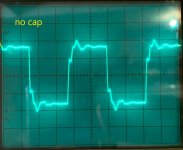
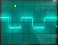
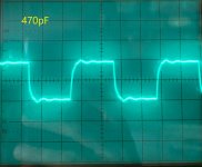
1. Feedback compenstation cap -- I bought 120pF, 270pF and 470pF caps to experiment. 10Khz squarewave was ugly without the cap. It got incrementally better up to 470pF.
Is this good enough or is it worth trying some higher values like 560pF ? (pics attached). OPT is Hammond 1650FA as FYI.
2. 270R cathode resistor -- I measured about 11.35V across which comes out to 42mA. With B+ around 320-325V comes out to about 13.5W dissipation, is that correct? Is it better to change this to 300R or 330R ?
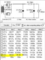
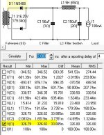
3. With the 370HX PT (550VCT), SS diodes and 193H choke (5H, 65R) B+ came out too high at around 350V. I put a 150ohm resistor in series with the choke temporarily and that brought it down to 325V.
I have a 270HX on order which has a 125V primary, along with a CL90 so hoping that will drop B+ a bit so a lower value resistor can be used.
Any other suggestions to bring B+ down?
Thanks !!
(You can ignore the question above regarding off-board sockets as I've went with all of them PCB mounted).
1. Feedback compenstation cap -- I bought 120pF, 270pF and 470pF caps to experiment. 10Khz squarewave was ugly without the cap. It got incrementally better up to 470pF.
Is this good enough or is it worth trying some higher values like 560pF ? (pics attached). OPT is Hammond 1650FA as FYI.
2. 270R cathode resistor -- I measured about 11.35V across which comes out to 42mA. With B+ around 320-325V comes out to about 13.5W dissipation, is that correct? Is it better to change this to 300R or 330R ?
3. With the 370HX PT (550VCT), SS diodes and 193H choke (5H, 65R) B+ came out too high at around 350V. I put a 150ohm resistor in series with the choke temporarily and that brought it down to 325V.
I have a 270HX on order which has a 125V primary, along with a CL90 so hoping that will drop B+ a bit so a lower value resistor can be used.
Any other suggestions to bring B+ down?
Thanks !!
Attachments
Last edited:
- Home
- More Vendors...
- Tubelab
- Tubelab Simple P-P