I finally put everything together.
This is a SPP connected in UL. PT is Edcor XPWR008 and OT's are Edcor CXPP25-MS-8K with a 23% tap. The enclosure is an Hammond with walnut. I wish I had gone metal. The enclosure is very is a bit small for this...
As luck would have it, I had on hand a blue spray paint that matches the Edcor bells. I also added a green 6.3 V jewel light. Looks like a old-timey guitar amp. I am waiting for a better pot (I have a Alps 50 on order).
Everything seems to work ok. The PT is barely warm after 1/2 hour, and so are the OT. I cannot say the same with the tubes
It only took two years...
Now to the next one...
Marco
View attachment 524414
Can you tell me size of the top plate of your amp? I like the layout of it. And the color...
Blake
Can you tell me size of the top plate of your amp? I like the layout of it. And the color...
Blake
Hello Blake:
Thanks!
I used an Hammond enclosure. The units itself can be found here:
https://www.tubesandmore.com/products/P-HWCHAS1310AL
and at many other places.
The dimensions are in the attached pdf.
Attachments
Thanks... For the chassis link.
I'm not crazy about the wooden framed chassis. Just yesterday after I posted my question I found the the DIYAudio store now offers metal chassis that are reasonably priced so I'm going to order one from here (there). The only thing is that it seems these are really designed for SS amps and have vented top plates. And I'll have to perhaps fabricate a new top plate.
I'm not crazy about the wooden framed chassis. Just yesterday after I posted my question I found the the DIYAudio store now offers metal chassis that are reasonably priced so I'm going to order one from here (there). The only thing is that it seems these are really designed for SS amps and have vented top plates. And I'll have to perhaps fabricate a new top plate.
Thanks for posting the link! I note that the enclosure uses 2mm Aluminium sheet for the top plate - how did you find the sturdiness - much flex with the transformers loaded up? My planned enclosure is simlar dimensions, but I spec'd 2.5mm after reading around, I'd be interested if I could get away with 2mm instead...I used an Hammond enclosure. The units itself can be found here:
https://www.tubesandmore.com/products/P-HWCHAS1310AL
and at many other places.
The dimensions are in the attached pdf.
Cheers,
Rob
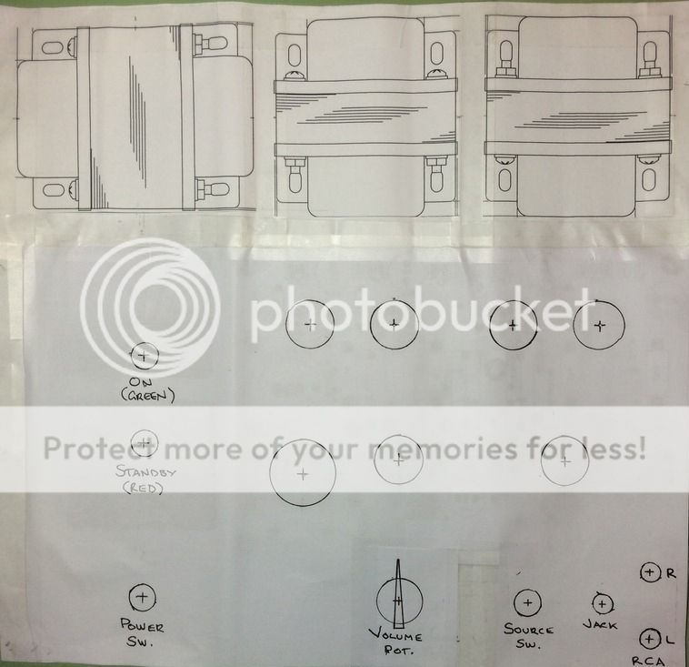
I revised my layout. All power transformer connections are now on left side. Red light shows the read panel IEC socket/switch/fuse is turned on, green light shows toggle switch has powered the amp on - lights are really just to fill up the available real estate.
All inputs, switch and volume are front/right on top plate close to PCB connections. Speaker terminals will be on the rear plate behind the output transformers. I've tried to balance/centre the tubes in front of the output transformers.
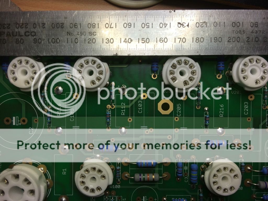
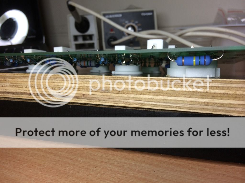
Started the soldering, got all the resistors and tube sockets done. Mounted the 9 pin sockets so the collars match the octal socket - quite happy with the alignment. Fingers crossed the rest of the project goes as well!
All inputs, switch and volume are front/right on top plate close to PCB connections. Speaker terminals will be on the rear plate behind the output transformers. I've tried to balance/centre the tubes in front of the output transformers.
An externally hosted image should be here but it was not working when we last tested it.
Started the soldering, got all the resistors and tube sockets done. Mounted the 9 pin sockets so the collars match the octal socket - quite happy with the alignment. Fingers crossed the rest of the project goes as well!
An externally hosted image should be here but it was not working when we last tested it.
Thanks for posting the link! I note that the enclosure uses 2mm Aluminium sheet for the top plate - how did you find the sturdiness - much flex with the transformers loaded up? My planned enclosure is simlar dimensions, but I spec'd 2.5mm after reading around, I'd be interested if I could get away with 2mm instead...
Cheers,
Rob
Hi Rob:
The Hammond enclosure has a lip all around and the corners are braced, so the top plate is well supported. I do not detect much flex, especially because the transformer are as close to the edges as I could place them. With these caveats, I think 2 mm is enough but depends on what you have.
Marco
Thanks for your reply Marco - I'll keep that in mind!The Hammond enclosure has a lip all around and the corners are braced, so the top plate is well supported. I do not detect much flex, especially because the transformer are as close to the edges as I could place them. With these caveats, I think 2 mm is enough but depends on what you have.
Rob,
Maybe read up a bit more on the standby switch - George (Tubelab) has a some words of caution regarding diodes blowing up with certain transformers with the use of a standby switch in the Tubelab SSE design:
Tubelab SSE | Tubelab
Not sure if same applies to the Tubelab PP - maybe others can chime in!
Last edited:
Maybe read up a bit more on the standby switch - George (Tubelab) has a some words of caution regarding diodes blowing up with certain transformers with the use of a standby switch in the Tubelab SSE design:Tubelab SSE | Tubelab Not sure if same applies to the Tubelab PP - maybe others can chime in!
Thanks for your concern and the link!
In truth, my standby switch is just a 'gimmick' to use up the space on the left of the board - as described in my post above. The whole circuit is pre the Power Transformer. The rear IEC power socket I'm using has a power switch on it: IEC Fuse Chassis Male Power Plug with Switch | Moulded Leads | Distribution & Interconnect | Power Products Electrical | PRODUCTS | PP4003 | Jaycar Electronics
When IEC switch is on, it powers the Red 240V panel light. The Power transformer (and therefore the rest of the amp) only recieves power once the Toggle is switched to on, which also powers on the green 240V light. Sorry I was not clearer in my previous post.
So it's not a traditional 'standby' like my Marshall 1962 Bluesbreaker guitar amp requires - just an affectation to balance the layout of my top deck! ;-)
Last edited:
So it's not a traditional 'standby' like my Marshall 1962 Bluesbreaker guitar amp requires - just an affectation to balance the layout of my top deck! ;-)
Cool and should look nice!
Hello everyone:
I will have to make some measurements before I do anything, but here are my observations: my build is rather compact, but the tubes do stick out of the amp top plate well. The transformers run cool, initially, but after about 1-2 hours, the amp top plate gets hot and so everything, including the transformers, gets hot.
It seems as if the EL84 are really heating up the works.
Is this normal or (as the measurements I have to make will answer for sure) is the B+ a bit high? Or could be simply a result of tight spaces around the tubes? I have posted a picture of the build a few posts back. In the build I use 5ar4 but I have handy several other rectifier tubes (5u4gt and 5y3). I know that the 5u4 will lower the B+ by adding "sag". Is this advisable?
Thanks!
Marco
I actually think that the transformed are not getting hot by themselves. The are heated by the sheet on top of the amp, which in turn is heated by the tubes. I am not really familiar with tube amps, so I don't know what "Hot" is really hot. The transformers are actually cool initially and stay so for 1/2 hour easily. It is when the metal sheet gets hot, that everything gets toasty.
I have checked a few voltages.
Line voltage here is a bit high, at 125 Volts (Not much I can do, unless I add a variac)
The output of the power transformer are 315-0-315 (5% higher than spec, probably due to the high line voltage).
B+ with the Chinese brand 5AR4 is 343V.
B+ with the American made but vintage 5U4GB is much lower, at 303V.
B+ with a vintage American made 5y3GT is only 282V (not good, I think)!
Out of completeness I checked the filament voltages: 7.0 V for the 6.3 tap and 4.9 for the 5.0 ( bit low. Probably due to the large current drain of the rectifier).
All measurements were made with volume at the halfway point, no input and my speakers connected to the 8 Ohm taps of the OPTs.
I am going to try the 5U4gb for a while (inrush voltage problems and all) and see how I like the amp with lower B+.
Marco
Last edited:
If you can keep your hand on the transformer for as long as you want, it's running at a safe temperature. If you can't hold it there for more than 5 or 6 seconds, it's something to be concerned about. The temperature of the plate is pro ably not that important as long as the chassis has some internal ventilation of some sort.
The amp is doing fine. It gets a bit toasty after about 2 hours, but I have come to the conclusion is because the footprint of my build is rather small, and I have got 7 tube heating up the works. No problems it looks like.
Today I had a bit of a "religious" experience:
I put on the "1812 overture" and cranked it up. I have fairly sensitive speakers (95db), and I had a blast (several, actually, if you know the piece...") ). This little amp does really sing!
). This little amp does really sing!
Thanks George!!!
Today I had a bit of a "religious" experience:
I put on the "1812 overture" and cranked it up. I have fairly sensitive speakers (95db), and I had a blast (several, actually, if you know the piece...
). This little amp does really sing!Thanks George!!!
Hey guys,
I've had my SPP running for about a year now, and I'm really happy with it. It runs pretty much 12 hours a day at the weekends, so there can't be anything too far wrong, but after a few hours use, my PT and top late are hot to touch, i.e. I can't keep my hand on them for more than a few seconds. I am a bit worried about heat and the effect that might have on longevity. Also, my PT vibrates and one of the end bells has a quiet ring to it.
There's a picture of my amp in this post. I'm using the Edcor XPWR066 PT and CXPP25-MS-7.6K OPTs, Russian Reflektor 6P14P-ER power valves, Brimar CV4024s, and a Sovtek 5AR4.
I have ordered a choke to replace R1 in order to remove the heat that R1 currently dissipates into the top plate. I'm planning on drilling some ventilation holes in the top plate around the power valves (as well as the ones already in the base plate.) I'm also planning on mechanically isolating the PT from the top plate using some silicone grommets to hopefully fix the ringing. If I do so, what's the best way to ensure that the PT is grounded? I ground the paint off one of the PT's "feet" to ensure electrical continuity between the PT and the top plate, and I'm not sure of the best way to do that with silicone spacers in between - just grind it off the "top" of the foot and rely in the bolt?
Is there anything else I can do to cool down the PT? I've read that heat and vibration may be the result of DC in the mains, but I don't know how to test for that, or to fix it.
Cheers,
Jon
phyciocc
You may want to try appropriate resistors to reduce your 7V heater filament voltage to even 6V for better tube life!
jonwhitear
I use a quiet fan (or you could use computer fans with lower voltage wall warts so they run slower and quietly) ) on my old Eico HF-12's in which the PS Trans runs very hot and is known to and it cools everything down nicely. I think the tubes may even last longer from what I've read!
Last edited:
If I do so, what's the best way to ensure that the PT is grounded? I ground the paint off one of the PT's "feet" to ensure electrical continuity between the PT and the top plate, and I'm not sure of the best way to do that with silicone spacers in between - just grind it off the "top" of the foot and rely in the bolt?
Jon
Use tooth washers. These will bite into the tabs. You can also scrape the paint just where the washer meets the tab.
After doing that you should use your multimeter to check for continuity with the IEC adaptor ground pin or your star
ground point.
If you cannot keep your hand on the power transformer for more than a few seconds then it is getting too hot and
calls for further investigation.
Hi guys,
I tried out a few different feedback caps on the weekend, measuring each with 5KHz and 10KHz square waves, with 10R/5W loads. I'll upload the screen captures later. The 270pF cap looked best to me, so I soldered it in.
Trouble is, when I connected the amp back up to he speakers and powered it on, it made a very loud sound like an oscillating square wave, until I quickly shut it down.
Do you know why that might have happened?
Cheers,
Jon
- Home
- More Vendors...
- Tubelab
- Tubelab Simple P-P