Well I decided with all the extra parts left from my first Simple SE build I have enough left to do a second amp. I wanted to make this one a bit more unique and go with all capacitors to be non-electrolytics. I have the power supply covered and I am using all motor runs. For C1 I will be using a 50uf motor run, C2 100uf and an additional 150uf to be added. There was another member of the board that built a similar Simple SE so I have basically copied his power supply.
The area I am not too sure on is 6.3v 1500uf Cathode bypass cap. How low of a value can I go here. Finding large value film caps is hard/expensive. Also the the two caps at C12,C22 how much lower of a value can be used in place the 1500uf caps specified on the BOM. I figure this is going to get kind of expensive so it may not be feasible but I thought why not give it a try.
The area I am not too sure on is 6.3v 1500uf Cathode bypass cap. How low of a value can I go here. Finding large value film caps is hard/expensive. Also the the two caps at C12,C22 how much lower of a value can be used in place the 1500uf caps specified on the BOM. I figure this is going to get kind of expensive so it may not be feasible but I thought why not give it a try.
These are $23 each, but would work fine as a cathode bypass cap.
http://www.parts-express.com/pe/pshowdetl.cfm?PartNumber=027-447
http://www.parts-express.com/pe/pshowdetl.cfm?PartNumber=027-447
OK, I'll tell you how to make a non electrolytic Simple for very little money, but you will need to do some serious experimenting.
You already have the power supply figured out. Motor run caps. So build your board, wire in some motor run caps, leave the cathode bypass caps out, and test the board. The gain will be low without the caps, but you should still get sound. You can tack some caps on the back of the board to test if you want. It is always a good idea to start with a working board otherwize you won't know if your experiment was successful.
I use oversize capacitor values in my amplifier designs. There is a real reason for this despite what some "experts" say in other forums. I took a bunch of capacitors into work and tested them on a fancy HP component analyzer. Real capacitors are not perfect, they have a resistance and an inductance associated with them. I simply tested a bunch of caps and picked the ones that had the lowest ESR and ESL. I guess that is the engineer in me. I doubt that you han hear the difference with any good cap over 200uF.
OK, lets run with that. If we want NO CAP, how do we get NO CAP? Ask yourself, what would SY do? You guessed it LED's. Using an LED for the cathode of the 12AT7 works good. I have done it. No cap and no resistor, just an LED. The catch......you need the right LED. LED's are quite variable as to their forward voltage drop for different part numbers of the same color. 12AT7's are quite variable as to the cathode voltage required to get a reasonable plate voltage. The current is fixed by the CCS chip. It is possible that the two sections of a given tube are different enough to require two different colored LED's.
Finding the right LED requires some experimenting and a bunch of LED's. I soldered a pair of alligator clips on short wires into my board and started trying a bunch of LED's. You want an LED that puts the plate voltage in the 175 to 250 volt range. A more technical approach is to put your chosen 12AT7 in your working Simple SE and measure the cathode voltage. Then look for an LED that has that much forward voltage at 10 mA.
OK now what do you use for the cathode bypass in the output stage? I would be tempted to wire a few motor run caps together and hide them under the deck, but there may be other alternatives. LED's? Well yes this is possible, but it will take a BUNCH of LED's. Yes, I have tried it. Yes it works, and yes the amp lights up the whole room! I have a friend who builds all sorts of Gizmos using PIC chips and LED's and he buys LED's by the hundreds from a vendor in Hong Kong. There are some big LEDs available now that operate at 100+ mA and drop 3 or 4 volts. They are blue or white and are often sold as "1 watt" LED's even though they run at about 1/2 watt. He brought over a bunch and we wired some into a Simple SE. I think we had 12 in series in each channel to get the current right.
Another possibility is to use a big zener diode. It would take a 10 watt zener diode. The voltage would need to be the same as the cathode voltage measured on the same tubes in the board with cathode resistors. I have not tried this yet though.
It has been suggested to use fixed bias. I have done this, but a negative voltage source is required. This implies another power supply.
You already have the power supply figured out. Motor run caps. So build your board, wire in some motor run caps, leave the cathode bypass caps out, and test the board. The gain will be low without the caps, but you should still get sound. You can tack some caps on the back of the board to test if you want. It is always a good idea to start with a working board otherwize you won't know if your experiment was successful.
The area I am not too sure on is 6.3v 1500uf Cathode bypass cap. How low of a value can I go here.
I use oversize capacitor values in my amplifier designs. There is a real reason for this despite what some "experts" say in other forums. I took a bunch of capacitors into work and tested them on a fancy HP component analyzer. Real capacitors are not perfect, they have a resistance and an inductance associated with them. I simply tested a bunch of caps and picked the ones that had the lowest ESR and ESL. I guess that is the engineer in me. I doubt that you han hear the difference with any good cap over 200uF.
Remember, there is no cap like no cap.
OK, lets run with that. If we want NO CAP, how do we get NO CAP? Ask yourself, what would SY do? You guessed it LED's. Using an LED for the cathode of the 12AT7 works good. I have done it. No cap and no resistor, just an LED. The catch......you need the right LED. LED's are quite variable as to their forward voltage drop for different part numbers of the same color. 12AT7's are quite variable as to the cathode voltage required to get a reasonable plate voltage. The current is fixed by the CCS chip. It is possible that the two sections of a given tube are different enough to require two different colored LED's.
Finding the right LED requires some experimenting and a bunch of LED's. I soldered a pair of alligator clips on short wires into my board and started trying a bunch of LED's. You want an LED that puts the plate voltage in the 175 to 250 volt range. A more technical approach is to put your chosen 12AT7 in your working Simple SE and measure the cathode voltage. Then look for an LED that has that much forward voltage at 10 mA.
OK now what do you use for the cathode bypass in the output stage? I would be tempted to wire a few motor run caps together and hide them under the deck, but there may be other alternatives. LED's? Well yes this is possible, but it will take a BUNCH of LED's. Yes, I have tried it. Yes it works, and yes the amp lights up the whole room! I have a friend who builds all sorts of Gizmos using PIC chips and LED's and he buys LED's by the hundreds from a vendor in Hong Kong. There are some big LEDs available now that operate at 100+ mA and drop 3 or 4 volts. They are blue or white and are often sold as "1 watt" LED's even though they run at about 1/2 watt. He brought over a bunch and we wired some into a Simple SE. I think we had 12 in series in each channel to get the current right.
Another possibility is to use a big zener diode. It would take a 10 watt zener diode. The voltage would need to be the same as the cathode voltage measured on the same tubes in the board with cathode resistors. I have not tried this yet though.
It has been suggested to use fixed bias. I have done this, but a negative voltage source is required. This implies another power supply.
Some cathode loads proposed in this thread: http://www.diyaudio.com/forums/showthread.php?postid=1867965#post1867965
Also, you can use an LED or other similar load with a series resistor to linearize it further. So, something in between a bypassed resistor and a constant voltage load. Of course, gain is in between too.
Sheldon
Also, you can use an LED or other similar load with a series resistor to linearize it further. So, something in between a bypassed resistor and a constant voltage load. Of course, gain is in between too.
Sheldon
I doubt that you han hear the difference with any good cap over 200uF.
You can still find the red blackgate N series non-polarized 470uF 6.3V, for less then 10 bucks...
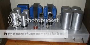
I did finish this project. It sounds great. I used four 600uf asc caps for the cathode bypass capacitors and the power supply is all motor runs. The downside....the amp is 2 feet wide.
Nic...I won't show this to my own SSE, as it would be totally embarrassed
with it's single, puny, motor run! Nice job!
I won't show this to my own SSE... it would be totally embarrassed
So, just how much difference does the oil filled poly cap make? As coincidence would have it, my Simple SE is playing tonight and I'd swear it has never sounded better. I still enjoy it as much as when I first built it - maybe even more. However, I never bothered to put the motor run cap in it.
I've got an extra 1.25 mfd cap around (out of a microwave oven). It's rated for 1200V (one thousand, two hundred volts). Sure, the capacitance rating is next to nothing - a spit in the ocean of aluminum electrolytic. Should I stick it in my Simple SE? Is it the extra mfds afforded by the motor run that make it special, or is it the deliciously low impedance characteristics that are magical? Or is it something else?
The low ESR is my guess, but theoretically it shouldn't matter for class A right? I have a couple of other film caps destined to become additional bypass caps to the cathode resistors. It's more of a curiosity to see how close I can get the SSE with EL34s to the TSE with 45s. Kind of a low priority, though. I am getting quite a backlog of amp projects for some reason. Same thing happened last time we had a baby. Stress therapy?
The low ESR is my guess, but theoretically it shouldn't matter for class A right?
I don't buy that theory. Sure, class A guarantees constant current draw - but only on average. There's going to be upswings and downswings of the input signal, and these swings have got to result in variations in current draw. Even if those excursions exist only for a fraction of a second (about 15 milliseconds for a deep C note, or 65.4 Hz) the supply caps must begin to discharge. Will that infinitesimal reduction in supply voltage be audible when the power supply starts to sag? Some people say our brain isn't fast enough to process that kind of information. I believe the human brain is better at recognizing differences in pitch (and intensity, and color, and brightness, and flavor, and temperature, etc) rather than absolute values. If the note is off pitch by a few Hz, eventually the "wrong" note will begin to sound "right" - as long as everything else is also off by the same factor. However, if the note changes pitch in mid-play, you'd better believe you're going to hear it.
I'm an engineer by trade, and I've never studied physiology or psychology or anything that might relate to the human perception of our environment. I like math and hard facts and proven theories. These assumptions I've based only on my own experiences and on what little material I've read in a casual environment.
Bless you and your family on your new addition. Stressful at times, yes. But definitely worth it.

I've got an extra 1.25 mfd cap around (out of a microwave oven). It's rated for 1200V (one thousand, two hundred volts). Sure, the capacitance rating is next to nothing - a spit in the ocean of aluminum electrolytic. Should I stick it in my Simple SE? Is it the extra mfds afforded by the motor run that make it special, or is it the deliciously low impedance characteristics that are magical? Or is it something else?
The low ESR is my guess, but theoretically it shouldn't matter for class A right?
I don't buy that theory.
In an SE amp the output impedance of the power supply is in series with the OPT. In a stereo amp the impedance is in series with both OPT's. Every power supply has a finite output impedance. If the output impedance is a pure resistance the only ill effects would be a slight loss of power and channel seperation. The problem arises due to the fact that the output impedance of the power supply is a complex impedance with a few other factors thrown in.
An electrolytic capacitor has an ESR. This is the Effective Series Resistance associated with the capacitor. It is usually specified at a single frequency and is not constant with applied frequency and temperature. There is an ESL, the Inductance component, which is also not constant, and a few other factors. These will result in the output impedance of the power supply being non constant across frequency, and having reactive components capable of creating phase shifts, or worse creating resonances with the reactive components of the OPT's. There are some time related storage factors too (dissipation factor, and loss tangent).
Ideally we want a power supply with a low, constant, and non reactive (pure resistance) output impedance from DC up to the cutoff frequency of the OPT. The best way to do this is a regulated supply using a bunch of feedback (kind of like a big SS amp with a DC offset problem). The cheapest way is to chose an output capacitor in the power supply with good ESR characteristics up to 100KHz. There are some good electrolytics available, but none are as good as a good film cap. Most motor run caps that I have tested exhibit good characteristics but tend to be big.
It is a standard practice by many DIYers and some tweakers to install low value film caps across the electrolytics in the power supply and cathode bypass. This can work, but it can backfire. It is entirely possible for the capacitance of the film cap to resonate with the incuctance of the electrolytic in the audio band, or in the frequency range just above the audio spectrum. This can make the amp sound worse than an electrolytic alone.
Will your microwave oven cap make things better or worse? This one is hard to call. Microwave ovens are made as cheaply as possible, but that cap passes considerable AC current so it is probably decent. I would say try it and see. Many proponents of the big caps report obvious audible improvements, and I tend to agree here.
You can see the results on a scope too. If your scope can be connected directly across the B+ without damage, connect it, set it on AC coupling and a sensitive range. Fire up the amp and run it to the edge of clipping. Ideally you should see nothing. Add cap, repeat. I will run this test with an audio generator and dummy load, sweeping from 5 Hz to 100 KHz, and then again with music and speakers. Play something loud and bang the amp into clipping. You should see a reduction in crud when the cap is added.
....snip.... my Simple SE is playing tonight and I'd swear it has never sounded better. I still enjoy it as much as when I first built it - maybe even more. However, I never bothered to put the motor run cap in it...snip...Or is it something else?
Ty...are you still using the 6P3S-E's in your SSE? Since you turned me on to those, I've put my KT88's back in their boxes. With an 800 R resistor giving around 47ma, the music is wonderful. They do need a real good warmup though...after a couple of hours they are at their best. And it does seem to get even better over time. If you're still using the Russians, maybe that's what you're hearing? (And the blue glow on the glass is cool with the lights turned out!)
It is entirely possible for the capacitance of the film cap to resonate with the incuctance of the electrolytic in the audio band, or in the frequency range just above the audio spectrum. This can make the amp sound worse than an electrolytic alone.
Well, the 'lytic on the cathode resistors is a low impedance Nichicon and the film cap slated to live there is a Solen Fastcap. We'll see what happens. When the SSE sees the bench, it will be subjected to various torture tests.
Ty...are you still using the 6P3S-E's in your SSE?
These can be had for a good price, but the specs keep me away. How much B+ are you guys running on these?
These can be had for a good price, but the specs keep me away. How much B+ are you guys running on these?
Shhh....I don't want the Russians to raise the prices...

My SSE has around 425V B+. The tubes show no distress. No red plates. No grids (that I can see) glowing abnormally. The sound is crystal clear with a nice "tube" sound that reminds me of the 6550's I've used in the past.
I've read elsewhere that the quality of the 6P3S-E can be spotty. Indeed, one of quad I bought failed to light. But it was due to the common Russian problem of bad pin soldering. I hit the pins with a Weller, and all was good.
- Status
- This old topic is closed. If you want to reopen this topic, contact a moderator using the "Report Post" button.
- Home
- More Vendors...
- Tubelab
- Electrolyticless Tubelab Simple SE