PaulyT said:Apologies for being dense, but I'm still a bit confused about C4:
I use choke for R4 as well and what I ended up doing to get the B+ voltage I want was to purchase 3 extra caps for C4 with the value that is half of each descending order (+- 22, 10, 5 etc.). The voltage I get from the outlets of my place may not be same as George's or someone else's place. Those caps are cheap compare to other parts especially the smaller values. I soldered and desoldered C4 a few times to get the right voltage. It should be doable if you use the soldering iron with right temp and wattage. Mine is set at 590 dF and puts out 60W.
Let us know how the voltages work when all the tubes are in.
PaulyT said:I'm using your PT.George's manual says: "Some users will substitute an external choke for R4. This will require modifying the value of C4 to get the proper voltage, which is now dependent on the value of the choke and the value of C4."
I think he phrases it that way because the power supply is designed for a 150 ohm resistor in the CRC filter and now it is a CLC filter. If you use the cheap 6H Triad choke that he mentions, it just so happens to have 150 ohm DCR and so you should get about the same B+ as the CRC version. If you use a different choke with a lower DCR, then you may end up with more B+ which may not be what you want. You can compensate for this by dropping the value of C4.
I used a Hammond 193J in my tests, which has a 82 ohm DCR. So the B+ in my amp may be a little higher than someone using the Triad choke or just the resistor. In the end, it doesn't make a huge difference. Someone using a hotter transformer or maybe 400V caps in the filter section or perhaps vintage NO$ globe 45's might worry more about the final B+ being a little too high.
boywonder said:Use a good quality electrolytic cap for C8/C10 (4700 6.3V). Black Gates are highly regarded and (reasonably) affordable for this location at about $14/ea for 16V std quality caps.
Thanks, that sounds like a good choice. I've ordered a couple of the Black Gates for this.
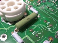
rknize said:Speaking of R6...make sure you upgrade that sucker to a 7W or higher! He mentions this on his front page and in the instructions, but his parts list still specs a 5W. I put Digikey PPC7W10.0KCT-ND
there, but even it is being pushed hard. It's fine in open air, but if you are planning to flush-mount this board, I would consider what I am doing...mounting a chassis mount 10W, 1k resistor to the chassis.
Ok, I can get a 10W, but these things, at least the wirewound type, are like 1.8 inches long... guess I could fit it on the spot for R6 if I raise it up a bit? I'm not doing anything fancy with the mounting, planning to put all components on the top of the board. I wouldn't really want to put R6 under the board anyway, for ventilation reasons. Are there other more compact alternatives? Does it matter if it's wirewound or some other type? (I'm guessing not.)
What about something like this thick film planar resistor?
Evenharmonics said:Pauly T, what George used on his board will do just fine. No need to spend more than what he did. OPT may be another matter but he has EP on his TSE.
Talking about the power transformer? Yeah, I'm getting an Edcor, ~$62 or so. And yes, I've ordered EP OPTs ($125 ea.). I realize I'm not making the world's cheapest TSE amp... but I don't want to think "should I have upgraded?" later on.
Well, I'm not getting that one because they're $7 each and you have to buy 5... The one I linked to above is ~25mm on a side (so it's also 25mm high). The only issue is that its pins are narrow, so I'd have to fudge a bit with some leads to extend it to the holes in the board. Not a huge deal, I think. My main question is, does it matter what type of resistor is used as long as the specs are the same?
I would say there is not much point in putting a good cap in that position. In fact, going to a cap with lower ESR is only going to make the rectifier work harder for not much gain. If you are going to bypass the 120uF cap with a film or foil cap, there isn't much point in sinking more money there either unless you want to completely replace C5 with a film and/or foil cap.
Law of diminishing returns sets in at some point here, but that point is entirely up to you. It's easy to get caught-up in all the boutique stuff and I fell prey to that for a while back int he day as well. I was spending money buying holcos when i should have been buying new speakers instead. Completely a personal choice at this point.
I have the best Panasonic I could find for the C8/C10 caps. My plan was to bypass those with a film cap, but I didn't get to it quite yet.
PaulyT said:Well, finally got all the parts ordered from various places, should be able to start assembly next week!
I got notification that Edcor was shipping my xfmr yesterday... they must have wound them in the same batch. I put mine on the slow boat so it won't get here until next week. I'll start the chassis this weekend to prep.
My SSE isn't even completely finished yet! I really should add the AC power light, tighten up all the connections and put in the variable cathode resistor board I wired up... ahh, cutting the grass can wait another week
I've ordered the Edcor PWT, but at the time they said it'll be 4 weeks (~3 now)... haven't heard otherwise. I can do the component soldering part of the assembly though, which should be relatively straightforward; just won't be able to do any power-up and voltage adjustments for a while.
As you say, there's (unfortunately) always other stuff to do...
As you say, there's (unfortunately) always other stuff to do...
PaulyT said:
Ok, I can get a 10W, but these things, at least the wirewound type, are like 1.8 inches long... guess I could fit it on the spot for R6 if I raise it up a bit? I'm not doing anything fancy with the mounting, planning to put all components on the top of the board. I wouldn't really want to put R6 under the board anyway, for ventilation reasons. Are there other more compact alternatives? Does it matter if it's wirewound or some other type? (I'm guessing not.)
What about something like this thick film planar resistor?
Never got a response on this one. Attached is an image of this resistor, any reason not to use it at R6? If I face it away from the rectifier tube, it should provide adequate heat dissipation. It's a 10k (5%) 10W.
Attachments
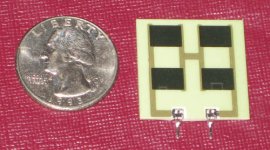
I checked out the specs, and it looks like the pin spacing is a little off .8" for the resistor vrs 1" for the PCB. You might be able to spread the legs on the resistor, but it might not like it either.
Why does resistor this need to be so high a wattage? I didn't think the negative rail used a lot of current...
I know the one I soldered on my board isn't a 10W.
Why does resistor this need to be so high a wattage? I didn't think the negative rail used a lot of current...
I know the one I soldered on my board isn't a 10W.
According to George's assembly instructions, R6 should be 5 or higher; he shows a 6.5. Russ said even 7 was getting hot...
Does it hurt anything to make the wattage too high?
Yes, the leads on this one are way too narrow to fit directly in the holes in the board. I'll have to solder some lead clippings on there to extend them, shouldn't be a big deal. But the width of the resistor itself is about right for that spot, unlike the higher-wattage more typical cylindrical wire-wound resistors which are very long (hence my seeking a substitute).
If you look at his front page and scroll down, there is a section towards the bottom about the Tubelab SE. He talks about R6 needing to be 7W or higher and also about the FET bias resistors. I posted about it here:
http://www.diyaudio.com/forums/showthread.php?postid=1845993#post1845993
The reason for the changes are likely because he conceived and designed the amp around the 45 tube, which only needs 300V of B+. When you kick the B+ to 400V by raising the high voltage winding, you are also adding 25% more voltage into the bias supply because he is getting the negative supply from the same winding through those FREDs. R6 is what brings that "B-" to a more reasonable voltage for the bias supply. The bias supply still becomes more negative though and that coupled with the higher B+ causes the FETs to have to dissipate more too (hence the changes to R14 and R25 as well).
This is mentioned in several places on his site (front page, the instructions, component value list, and the parts list) and they are all in different states of being up-to-date. Too bad his site's not a Wiki...I'd just fix it for him.
- Status
- This old topic is closed. If you want to reopen this topic, contact a moderator using the "Report Post" button.
- Home
- More Vendors...
- Tubelab
- Joining the Tubelab SE club