Is it cool to post pictures and questions about my Tubelab SE build here? I don't want to thread jack.
Doesn't bother me, but it might be more useful to start your own thread... those of us involved with this amp will see it.
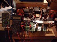
Ok, the 660v tap on the Edcor is pushing out more like 680 (+/- 10). The wall line is about 123V. The 5V and 6.3V taps on the Edcor measure about right, though my voltmeters aren't too precise in this range (their 200 VAC setting). So seems like input power is just fine. B+ is still hovering around 350V.
I guess I might need to tweak C4 (currently 47uF) to get a higher B+? It's not clear from George's manual how a choke at R4 (Triad C14X, 6H) will affect this balance... Any suggestions? George talks about a chart to determine this, but I don't see it anywhere in the instructions...?
One other small observation: these tiny panasonic resistors e.g. at R18/29 are kinda delicate... hard to hook up the minigrabbers to these without bending the hell out of the leads, I feel like it's about to get yanked out of the board.
I would try something around 50 - 55 uF for C4. I use Triad C14X in place of R4 and it works fine for voltage change by swapping out C4.I guess I might need to tweak C4 (currently 47uF) to get a higher B+? It's not clear from George's manual how a choke at R4 (Triad C14X, 6H) will affect this balance... Any suggestions? George talks about a chart to determine this, but I don't see it anywhere in the instructions...?
Did you leave enough lead slack when soldering on the board? They are fragile for sure and you just have to be careful when putting and removing grabbers on them. Either that or have spare resistors.One other small observation: these tiny panasonic resistors e.g. at R18/29 are kinda delicate... hard to hook up the minigrabbers to these without bending the hell out of the leads, I feel like it's about to get yanked out of the board.
Last edited:
The Triad choke has about the same DCR as the spec'd resistor. If you are looking for more B+, you can either drop the resistor value or go to the Hammond 193J choke, which has a DCR of 82ohms...IIRC. I wouldn't increase C4 any more since it is already on the high side for the 5AR4.
Where are you measuring B+?
Where are you measuring B+?
I wouldn't increase C4 any more since it is already on the high side for the 5AR4.
Hmmm... the manual says "The Amperex data sheet for the 5AR4 gives a maximum value of 60uF for this cap. " I'm using a GE. Is there somewhere to look up the data sheet for a GE 5AR4? Though IIRC Amperex and GE were basically the same company? Or are all 5AR4s more or less the same? I'll poke around a bit. I've ordered a 56uF of the same type as the spec'ed 47 (Panasonic), though I haven't received/installed it yet. I just don't understand why I've only got ~350V when George says he's getting 390V with a 660V PT. Do I have a bad rectifier, or different (incorrect) components, or...? I'm not sure, I was just expecting it to be higher.
Where are you measuring B+?
Across R30.
If he is using choke in place of R4, there shouldn't be a resistor there, only choke, no?Do you have another rectifier to try? It sounds like maybe this one is soft. Are you using the 150-ohm resistor for R4?
OK, you inspired me to dust off the TSE. I reconfigured it for 300B action and tried to set it up similar to yours. With the bias at 60mA per tube and the variac turned down slightly to get 660VAC (was at 670 at line level), I get around 374VDC B+.
Attachments
I've only got ~350V when George says he's getting 390V with a 660V PT
I haven't seen 390V in quite a while. Even though nothing has changed in the amp its B+ voltage is now 360 to 370 volts. In the past 2 years the distortion on our power lines is increasing. I measure 10 to 12% in the evening when everybody is watching their flat screen TV, and 5 or 6% after midnight. The B+ voltage goes down as all of the non PFC devices are turned on, since they all draw current only on the crest of the sine wave just like our tube amps.
Ok, thanks George. What do you think about the capacitance of C4, given that I'm using the C14X choke at R4? Should I bump up to 56uF (from 47 in the parts list), if switching to the Sovtek rectifier doesn't change things much? (yet to be seen...) I notice the rectifier is pumping out a lot of heat, probably the hottest thing aside from the 300Bs, but maybe that's normal. Would increasing the capacitance of C4 (and presumably hence B+) aggravate that?
PaulyT,
It is normal for the rectifier to be really hot. I used 4 types of rectifier from Mullard to Sovtek and can’t discern a difference. My B+ is around 330-345V. Are we to expect improvement if we bump the B+ higher? In my experience, 30 to 50V B+ swing did not change anything sound wise. The most important determinant for the sound in this amp were the 300Bs and the OPTs. I tried Valve Art, Shuguang, EH, and JJ and the best sounding for me were the JJs. I wish I can try WE or EAT. My OPTs are Electra Print.
Godspeed.
John Revilla
There's also Sophia Electric's which I would have tried if it wasn't for the recession.PaulyT,
I tried Valve Art, Shuguang, EH, and JJ and the best sounding for me were the JJs. I wish I can try WE or EAT.
Last edited:
Thanks guys! Yeah, I'm not sure I can quite justify the expense of trying multiple sets of 300Bs at this point... there aren't any "cheap" ones around that I know of.
Well, as I said before, maybe I'm making too much of the whole B+ thing, I'll try to do some comparison in both sound and B+ measurements between the sovtek and GE 5AR4s, see if I can discern any difference... I guess I can hook up my good speakers now that I'm reasonably confident they won't blow up.")
Well, as I said before, maybe I'm making too much of the whole B+ thing, I'll try to do some comparison in both sound and B+ measurements between the sovtek and GE 5AR4s, see if I can discern any difference... I guess I can hook up my good speakers now that I'm reasonably confident they won't blow up.
Lifting up the tubes
Hi all,
The discussions in this forum were very helpful in answering some of the questions that I had about Tubelab SE and I am getting close to ordering the parts.
In my amp I would like to have the tubes and the trannies exposed with everything else hidden in the box. George (tubelab) mentions on his site that this can be achieved by installing the caps on the back side of the PCB but it does not seem to be a straightforward task.
The other alternative I am thinking of is using wires from the PCB to the tube sockets that would be installed on the top plate but I am not sure if how hard this would be or if it would introduce any problems.
Has anyone tried doing something like this? I would appreciate any feedback or alternative ideas on how to lift up the tubes.
Thanks!
That works well for Tubelab Simple SE but not for Tubelab SE due to heat sink installation for semiconductors.In my amp I would like to have the tubes and the trannies exposed with everything else hidden in the box. George (tubelab) mentions on his site that this can be achieved by installing the caps on the back side of the PCB but it does not seem to be a straightforward task.
This is what I did for my TSE.The other alternative I am thinking of is using wires from the PCB to the tube sockets that would be installed on the top plate but I am not sure if how hard this would be or if it would introduce any problems.
Has anyone tried doing something like this? I would appreciate any feedback or alternative ideas on how to lift up the tubes.
- Status
- This old topic is closed. If you want to reopen this topic, contact a moderator using the "Report Post" button.
- Home
- More Vendors...
- Tubelab
- Joining the Tubelab SE club