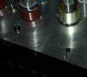
I'm still working on the case for my tubelab se amp, and am wanting to bring the bias test points to the chassis. Each time I switch tubes, it has to be re-calibrated.
I have the PCB stuffed w/ all the tall components on the bottom, so the board will be about an inch below the top of the chassis. (the height of the 4pin sockets)
I haven't decided if I'm going w/ wood or aluminum for the top. If I go with wood I was thinking I'd just drill very small holes and push wire through it. I'd leave just enough exposed to clip the meter leads onto. (I still have to figure out the details, but maybe I could come up w. small rubber caps for the wires, to keep the b+ voltage from actually being exposed)
If I go w/ aluminum, things will be more difficult. I'll have to use something insulated. The top of the amp will be exposed, so I don't want anything too large.
Would running ~4" wires to the back of the case to some jacks be a bad idea? I don't want to add antenna to the amp.
Any ideas?
Thanks!
That is exactly what I need.
Is there a problem running 4 or 5 inch wires from the test points on the PCB to the back of the chassis, or should I do everything I can to keep them as short as possible? (which will mean mounting them to the top of the chassis)
For those unfamiliar w/ the tubelab, I need to measure the current from B+ to the output tx for each channel, and also the voltage from the input tube plate to ground.
Something tells me I don't want extra wires hanging off of those points, but I'm not sure........
thanks!
I have a set of "tip jacks" wired into one of my amps on the output tubes. I simply soldered a pair of wires right on the 10 ohm resistors, twisted them, and ran them to the rear panel. Total length is about 4 inches. These wires do not have much AC signal on them, so they are not critical.
I have not tried putting jacks on the input tubes, and the plate of the 5842 does have considerable AC signal present. You can try it, run the wire, twisted with a ground wire to a pair of tip jacks. Keep these away from the input wiring.
The 5842 does like to oscillate under certain conditions. I have found that increasing the grid stopper on the 5842 from 1K to 4.7K fixed this under all conditions that I tested. These and other updates will be posted to the web site tonight.
- Status
- This old topic is closed. If you want to reopen this topic, contact a moderator using the "Report Post" button.
