Recently I have asked questions about AC coupled OPT for valve circuits, and well...let's be honest...I got a little frustrated by the seemingly rule-less selection of OPTs by impedance ratio, and then flamed slightly for quoting my transformer impedance as being the same as the impedance ratio...
So to educate myself, and hopefully show myself that I am not as dumb as some of the more simple comments would imply, I am investigating a number of transformers for suitability in my headphone amp circuit.
Now I have stated that I believe my valve circuit likes a reflected load impedance of 15k to shine, and deliver good THD results (<1%) @ 1kHz.
This was based on the calculated Impedance Ratio of a RS 30VA toroid (196-505):
N = 6.7
N^2 = 45
45*330R = about 15k with 330R headphones.
Q1: But what relevance is the Impedance Ratio?
It defines the output voltage, hence power output
Q2: Does measured Impedance Bandwidth stand close to impedance Ratio?
I am testing this
Q3: Which parameter is relevant here? Z ratio or Z BW? Both?
I hope to find out
Testing
Thank to PRR for the suggestion to measure impedance via potential divider method, at the time the obvious method escaped me. No excuses for that haha.
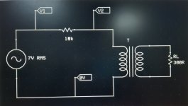
Attached below is my test circuit (essentially the same as PRR attached, but with more practical value of resistance - 1M is far too much)
Switching to using 10k resistor, mainly due to my expectation that I would measure transformer impedance in the order of 10k, gives me much better span of voltage to work with : I.e. half signal voltage when Z = R = 10k
For comparison I have:
RS 30VA toroid 196-505 (N = 6.7, N^2 = 45, Zratio = 15k)
RS toroid 1.6/3.2VA (N = 7.6, N^2 = 58, Zratio = 19k)
I need to redouble my efforts here and recheck the volts on unloaded and loaded secondaries, but I'm confident the figures are close enough
Also I have a gapped SE OPT which I think I can push into giving me a reflected load of the same order, for the sake of comparison.
Jan W. ATRA0288 4k/5k2: 4/8 SE OPT, which I expected would give about 10k reflected load with 16R or more on the 8R secondary.
I expect that the SE OPT may show me the way the Impedance BW should look and highlight the failings of using a mains toroid for a AC coupled OPT.
But it may not turn out that way
I already know it didn't quite come out so cut and dried....
Thank to PRR for the suggestion to measure impedance via potential divider method, at the time the obvious method escaped me. No excuses for that haha.
Attached below is my test circuit (essentially the same as PRR attached, but with more practical value of resistance - 1M is far too much)
Switching to using 10k resistor, mainly due to my expectation that I would measure transformer impedance in the order of 10k, gives me much better span of voltage to work with : I.e. half signal voltage when Z = R = 10k
For comparison I have:
RS 30VA toroid 196-505 (N = 6.7, N^2 = 45, Zratio = 15k)
RS toroid 1.6/3.2VA (N = 7.6, N^2 = 58, Zratio = 19k)
I need to redouble my efforts here and recheck the volts on unloaded and loaded secondaries, but I'm confident the figures are close enough
Also I have a gapped SE OPT which I think I can push into giving me a reflected load of the same order, for the sake of comparison.
Jan W. ATRA0288 4k/5k2: 4/8 SE OPT, which I expected would give about 10k reflected load with 16R or more on the 8R secondary.
I expect that the SE OPT may show me the way the Impedance BW should look and highlight the failings of using a mains toroid for a AC coupled OPT.
But it may not turn out that way
I already know it didn't quite come out so cut and dried....
Attachments
Last edited:
Some results
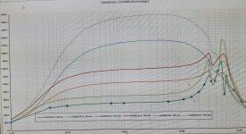
In the attached plot I have tested the SE OPT for a baseline comparison:
4k:8R - 8R load,
5k2:8R - 8R load,
Further curves for increased secondary load of 16R and 32R.
What leaps out at me is the rather large resonant peak, doublet/triplet of peaks in the range above 30kHz.
That's not nice, at all!!!
now I see why they were quite cheap...
As I'd expect the BW is reduced, with increased attenuation of both low and high frequencies, when the load resistance is increased.
In the case of this OPT however, running and increased secondary load is probably a good thing!
What else is noticable?
Well for one thing, with a Z ratio of 4k, the measured Impedance peak or plateau, is somewhat lower, 3k3.
In fact all measured impedance BW for all tapping are between 20% and 50% lower, with the situation worsening for greater increases in load resistance.
One configuration is close to my 10k to 15k target, the dashed blue curve, 4k:8 using 32R secondary load.
This gives about 10k impedance between 200Hz and 20kHz.
Attachments
Last edited:
Toroid-further comparisons
What started this was my original circuit, using RS 196505 30VA toroidal main transformer as OPT, and managing to achieve a pretty decent 50mW output at less than 1% THD measured at 1kHz, and also 100Hz, but awful at 10kHz.
Does THD at 10kHz matter? Maybe, maybe not.
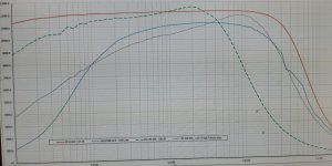
Referring to the attached plot,
The green dashed trace shows the impedance BW of the toroid; about 11k5 at 100Hz, and about 12k at 1kHz, with peak Z at 2kHz.
Impedance drops like the proverbial stone after 3kHz, and THD rockets to 5% or more at 10kHz.
Interestingly, primary Z has seemingly more influence than anything else.
In the Violet trace, I have paralleled the Secondaries, and only use one primary winding, for 115: 15V essentially keeping the ratio very similar, but reducing the primary inductance or lossy capacitance (truth be told I'm not sure exactly which is more at play here)
The results are middling - better Impedance at high frequencies, balanced by loss of loading at LF and lower overall impedance across the BW. Shame.
The little RS 1.6/3.2VA toroid is a bit of a surprise.
Using all windings whether in series or parallel, to preserve turns ratio, lead to a Impedance BW which was already in decline by 1kHz - no good for audio I guess!!!
Taking a look at the Red curve and, to my non expert eye, the Impedance BW is really quite impressive, 12k loading from about 50Hz to 18kHz.
So, is that what I am looking for, as a good Impedance load for my valve circuits?
Flat, non resonant, extended BW?
Should I really be designing for REAL impedance BW rather than Z ratio?
Or rather, should I be saying to myself:
" I want a Z ratio of 15k, but I know that real Z will be 25-50% lower than this; so instead I'll opt for a Z ratio which is 25-50% high, in order to accommodate this?"
Any answers on a postcard, SAE or comments, are welcome.
Thanks.
What started this was my original circuit, using RS 196505 30VA toroidal main transformer as OPT, and managing to achieve a pretty decent 50mW output at less than 1% THD measured at 1kHz, and also 100Hz, but awful at 10kHz.
Does THD at 10kHz matter? Maybe, maybe not.
Referring to the attached plot,
The green dashed trace shows the impedance BW of the toroid; about 11k5 at 100Hz, and about 12k at 1kHz, with peak Z at 2kHz.
Impedance drops like the proverbial stone after 3kHz, and THD rockets to 5% or more at 10kHz.
Interestingly, primary Z has seemingly more influence than anything else.
In the Violet trace, I have paralleled the Secondaries, and only use one primary winding, for 115: 15V essentially keeping the ratio very similar, but reducing the primary inductance or lossy capacitance (truth be told I'm not sure exactly which is more at play here)
The results are middling - better Impedance at high frequencies, balanced by loss of loading at LF and lower overall impedance across the BW. Shame.
The little RS 1.6/3.2VA toroid is a bit of a surprise.
Using all windings whether in series or parallel, to preserve turns ratio, lead to a Impedance BW which was already in decline by 1kHz - no good for audio I guess!!!
Taking a look at the Red curve and, to my non expert eye, the Impedance BW is really quite impressive, 12k loading from about 50Hz to 18kHz.
So, is that what I am looking for, as a good Impedance load for my valve circuits?
Flat, non resonant, extended BW?
Should I really be designing for REAL impedance BW rather than Z ratio?
Or rather, should I be saying to myself:
" I want a Z ratio of 15k, but I know that real Z will be 25-50% lower than this; so instead I'll opt for a Z ratio which is 25-50% high, in order to accommodate this?"
Any answers on a postcard, SAE or comments, are welcome.
Thanks.
Attachments
Having sat and considered my test setup, I may have done something slightly wrong...oops
Measuring volt drop across the series resistance, and using that difference voltage to calculate the current through Rs. Then using that current value with the voltage divider tap, to calculate Z.
All the while assuming the level I set on the Sig Gen is what is output at all frequencies.
Using 330k rather than 10k series resistance and I get a different result.
What am I doing wrong here? With a higher Rs I am left with small voltages to measure.
So I set about inserting a microammeter in circuit to check my results.
With uAmmeter in circuit my AC current readings tie up with calculated (10k Rs), and also when using 330k load, within reasonable tolerance, considering the measurement is between 20 and 500uA to the limits of DMM AC current accuracy (15kHz).
So perhaps my method is not at fault.
Which leaves inaccuracy of voltage measurements when using 330k Rs for the difference in results, where Rs is 10k and 330k.
Any further discrepancy, I guess is due magnetisation losses at lower AC current.
Though ìm probably missing something else, and some reader will be having a good old chuckle!
Last edited:
Any ideas?
Or advice?
Am I right to be using a smaller value of Rs like 10k to measure impedance of the transformer?
My reasoning for not using 1M (referring to PRR posted circuit):
*Larger signal to measure, reduced measurement error when using 10:1 scope probes.
*less influence on readings from measurement instrument (using Rs of 1M, and scope input impedance of 10M, some loss of signal is expected)
*Testing the transformer with AC currents that are closer to what it would experience, in use.
My doubts:
*Using 1M and 1V signal, as in PRR example, is the assumption made that the R is high enough to be considered a constant current source? I.e. 1uA - if so then this could explain the differences.
I think you are going way over the top with regards to expectations of a mains transformer in your application . I find using toroids as output transformers fine , as long as you drive with a low impedence . You would be better off having some custom transformers wound which fit your specifications . I am pretty sure there are also some pro-audio transformers with 10K primary and 150 ohm secondary which may be suitable , try Canford Audio
316a
316a
Hi and thanks for your input.
I am trying to establish how important OPT impedance is with respect to Impedance ratio.
In my plots above I test a gapped SE OPT designed for up to 60mA DC bias and 5W output, with 4k and 5k2 primaries.
Neither of these 'reflected loads' is what I would call close to the stated Impedance ratio, being up to 50% lower.
So while I can take a DC loadline to give me a turns ratio, impedance ratio, the AC loadline is thrown out by the lower impedance presented to the valve.
Currently a impedance ratio of about 15k:300R suits well for output and THD, as long as the Actual Impedance stays above 12k.
The "best" plot for flat, non resonant transformer impedance bandwidth is the tiny RS 1.6VA toroid, which maintains its measured impedance well above my hearing capacity (20Hz to 18kHz or so) and so looked like perfect match, and at £4 each....
The ideal turns ratio, for output, found experimentally, is somewhat lower than N = 8.1, more like 6.5 to 7.
There is nothing I can find, with a turns ratio of 7, Z ratio of 49 - to give near 15k:300R, or 30k:600R.
I found one, I think 25k:600R Lundahl or Sowter... but the DCR is very very high and I dont think the unit is good for signals over line level, HF loss is mentioned in some apps, on this particular model.
So far the nearest OPT I have found is N=8.1, Edcore XSM 10k/600R, with the centre tap (150R) being used for my 300R Sennheiser cans.
This ratio loses me something like 1/4 of the output level, probably about 3 or 4 dB which is a pain.
This translates into reflected load of 20k, I'm guessing the actual impedance presented would be somewhat lower, maybe 15k, and so it may be a good match for THD, even if I lose 15mW output in the process.
Custom OPT arent an option, standard ones are costly enough...
Put in perspective, this build has cost me: £4 for all the valves, £2 for the perf boards, a couple of D cells, and time")
So... spending £100 each for OPTs wouldnt just be a false economy, maybe building the lily a little?
I am trying to establish how important OPT impedance is with respect to Impedance ratio.
In my plots above I test a gapped SE OPT designed for up to 60mA DC bias and 5W output, with 4k and 5k2 primaries.
Neither of these 'reflected loads' is what I would call close to the stated Impedance ratio, being up to 50% lower.
So while I can take a DC loadline to give me a turns ratio, impedance ratio, the AC loadline is thrown out by the lower impedance presented to the valve.
Currently a impedance ratio of about 15k:300R suits well for output and THD, as long as the Actual Impedance stays above 12k.
The "best" plot for flat, non resonant transformer impedance bandwidth is the tiny RS 1.6VA toroid, which maintains its measured impedance well above my hearing capacity (20Hz to 18kHz or so) and so looked like perfect match, and at £4 each....
The ideal turns ratio, for output, found experimentally, is somewhat lower than N = 8.1, more like 6.5 to 7.
There is nothing I can find, with a turns ratio of 7, Z ratio of 49 - to give near 15k:300R, or 30k:600R.
I found one, I think 25k:600R Lundahl or Sowter... but the DCR is very very high and I dont think the unit is good for signals over line level, HF loss is mentioned in some apps, on this particular model.
So far the nearest OPT I have found is N=8.1, Edcore XSM 10k/600R, with the centre tap (150R) being used for my 300R Sennheiser cans.
This ratio loses me something like 1/4 of the output level, probably about 3 or 4 dB which is a pain.
This translates into reflected load of 20k, I'm guessing the actual impedance presented would be somewhat lower, maybe 15k, and so it may be a good match for THD, even if I lose 15mW output in the process.
Custom OPT arent an option, standard ones are costly enough...
Put in perspective, this build has cost me: £4 for all the valves, £2 for the perf boards, a couple of D cells, and time
So... spending £100 each for OPTs wouldnt just be a false economy, maybe building the lily a little?
Last edited:
I should also state that this experiment and circuit is for me to learn what is possible with cheap russian DHP to drive 300R cans.
Perhaps I expect too much?
I am confident that I could do a lot better using the 2W 1P24B output DHP instead - it would drive almost any headphones - but this is the challenge I set myself using a sub Watt valve.
Perhaps I expect too much?
I am confident that I could do a lot better using the 2W 1P24B output DHP instead - it would drive almost any headphones - but this is the challenge I set myself using a sub Watt valve.
I understand your comment about driving with a low impedance, only I dont really know what to consider "low".
I have seen folks use toroid with valves like 6C33 and other regulators, with ra in the region of 100R to 1k, at a guess.
I estimate the ra of these valves to be 5k, maybe less due to LNFB plate to grid.
I really need to verify this, and didn't get the lab time yet!
In circuit, I see no issue with bass roll off at all, which I would expect, if the source impedance driving the OPT was too high.
Also I see no degradation of THD until above 1kHz, and referring to the plot "RS 196 505_230:30" it's easy to see that the vast drop in impedance after 2kHz is probably responsible for this.
This isn't seen in the SET OPT plot (just a huge ultrasonic resonance).
It's very interesting to me that using one 0.8VA section of the RS 1.6VA toroid gives a beautifully flat impedance frequency response until well above the audio frequency range, no resonance, and a 2nd order curve beyond that (at a guess of order)
...10k/600R, with the centre tap (150R)
....1/4 of the output level, probably about 3 or 4 dB...
The center tap of "600r" is NOT 150r but 75r.
1/4 of the voltage is NOT 3-4dB but 6dB.
Yes, you're correct. My mistake.
That's a non starter then haha
Again my mistake and a estimate.
I could've said, about 0.8V out of a maximum output of 4V +/- 0.2V, with the toroid N=~7.6, (similarly to some 8.1:1 line matchers), versus another toroid with N=~6.7.
That's a non starter then haha
Again my mistake and a estimate.
I could've said, about 0.8V out of a maximum output of 4V +/- 0.2V, with the toroid N=~7.6, (similarly to some 8.1:1 line matchers), versus another toroid with N=~6.7.
Last edited:
So given that logic, if it can be considered so...
A N=7 OPT, N'=49:1 is what I need:
14k7:300R...obviously 15k would be fine.
I figured I could use Edcore XSM 10k/150
probably still my best bet, but again I lose the 15 or so mW...
Something like a Hammond 800a in 20k/24k:500/600 looks capable, but a maximum level of 20dBm without compromising the bandwidth....and expensive to boot.
Last edited:
Sorry but a center tap implies half the turns=half the voltage=1/4 the impedance.The center tap of "600r" is NOT 150r but 75r.
So the center tap of a 600 ohm winding IS 150 ohm. (relative to one end)
Sorry again but 1/4 the voltage is -12dB , NOT 6dB (to boot you should have written MINUS 6dB) and even less 3-4 dB of course.1/4 of the voltage is NOT 3-4dB but 6dB.
Sorry but a center
Sorry again but 1/4 the voltage is -12dB , NOT 6dB (to boot you should have written MINUS 6dB) and even less 3-4 dB of course.
Hang on.
-6dB is reduction by 50% in Voltage.
I have 25% reduction, so roughly speaking -3dB.
So...um yeah.
I was quite correct.
By power output (yes get ready I'll do some maths, my worstest least favourite ever subject)
-3dB is half power.
10log(34/53) = -1.93dB
So...again...I was quite accurate in my guess, to +/-1dB whether you consider voltage or power.
Last edited:
- Status
- This old topic is closed. If you want to reopen this topic, contact a moderator using the "Report Post" button.
- Home
- Member Areas
- The Lounge
- Transformer testing: Personal Journey