I used to work with an extremely competent engineer who built nice electronic circuits for gadgets.
He says the next thing was the Bean-counters (Accountants) would remove components to get the cost down... thing was, most of his components were there for a reason.
Puts on Bean-counter's Hat:
I'd get rid of the three impedance things on the left. Will anyone notice? We will make more money!
He says the next thing was the Bean-counters (Accountants) would remove components to get the cost down... thing was, most of his components were there for a reason.
Puts on Bean-counter's Hat:
I'd get rid of the three impedance things on the left. Will anyone notice? We will make more money!
Somewhat related to that, I actually agree with Joe that placing a series element (like inductor for woofers and capacitor/resistor for tweeters) as the last part in front of the driver is a good thing, for the simple reason it increases impedance the driver sees and thus can benefit from the reduced distortion with higher source impedance. For the same reason, don't pad down a tweeter with a resistor divider.
Like a partial current drive? Wouldn't it have to be quite large?
Back in 1976 I was a consultant for the Gibson (guitar and amp) company. The engineers there had made a pretty good solid state guitar preamp, that even I approved of. They originally used one of the first jfet input IC's, the LF356. Later, the bean counters forced them to be replaced by 741 IC's, and guess what? The product died in the marketplace. I could have told them that in advance, but it took years, even decades before the 741 was discarded for faster parts. It is the same today, the most sonically successful designs usually cost a bit more, because of higher parts quality, and only the serious listeners to subtle differences will believe that, and put their money or effort into it. Thank goodness some people really care about the differences.
You said "This equivalence test has already been peer reviewed,". Could we read that paper..It showed that proportional change in current gave proportional same dB change in SPL when a driver was compared under both current-drive and voltage-drive.
Richard probably added a small resistor as part of the negative feedback loop. This is not the same as just adding a resistor in series or parallel... I find current drive interesting but impractical for me. Great for DIY, especially with multi-amp drives. We haven't discovered 'everything' yet!
Thanks John. But I seem to have a problem in getting across that I am not into nor promoting current-drive.
Whenever I mention current, then you immediately get put into the current-drive camp. I have only ever built one transconductance amp and I then published it here. But I made it to be a tool for me, not the actual amplifier I listen too. Back in 2002 I was approached by people who needed help with Gainclones and got caught up into that and I came up with the tube buffered gainclone, which actually influenced others to also make commercial versions of them, which I allowed: Check this one, at least he gave me a credit.
So I turned a LM3575T into a current source - it does sound better than a normal gainclone, partly I believe because its current phase angle is always zero, and the smallish Class A transition into B means that current and voltage always line up inside the feedback loop. If they don't line up in Class AB amplifiers with feedback, then f/b is a voltage correction and is a very indirect method of correcting current. According to one Dutch source, high levels of high-order distortions can be the result. Your amps sans f/b would not have that problem.
But really, I was doing this gainclone thing because I loved DIY and loved helping people to do their thing. In the meantime, I have mainly been listening to tube amps and recently a reverse hybrid tube power amp, where the output is tubes (EL34) and the input is a solid-state differential circuit that can swing 2000V p/p if you have the power supply, I designed it and got it to the head of Power Electronics to computer-model the circuit and it came out a beauty. Low noise and super fast and clean, virtually distortion-free. Walt is the guy behind the electronics/guidance system used in SpaceX rockets. He is the son of a friend of mine, so that was fortunate.
But I digress, what I am really interested in is what the current is doing rather than current-drive.
This is entirely different because I actually want to hear the benefits of current-drive with voltage sources (would you like a reduction of the 7th by 15dB, nice?).
BTW, there is such a thing as voltage sources, but when you look at what both voltage and current does when it flows through a voice coil, you realise that there is no such thing as voltage-drive (now I have probably put my head on a chopping block saying that) and it is most obvious when looking at overhung voice coils, the part of the VC is usually about 70% of the length and sits outside that gap, is made of CCAW (copper-clad aluminum wire) with typical 4R and are basically acting as wire-wound resistors and are in series with the output impedance that is only a fraction of an Ohm. Call it what you like, that is not voltage-drive.
So it is stuff like that I am looking at, seeking out knowledgeable people and pointing these things out and they get surprised, but they also get the point.
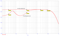
For example, design and make a loudspeaker, 2-Ways are everywhere, most that only sounds so-so. Make the amplifier produce the same current at all frequencies into the speaker, from DC to 20KHz. Use passive parallel components to accomplish it. Now you can connect it to any amplifier.
Now the output impedance has effectively canceled out, and the bass alignment stays put with any source impedance. But now comes the interesting part. The crossover becomes immune to the source impedance of the amplifier (see attach). All this is explained by simply tracking the current in the two drivers and you can measure the proportional output of both drivers down to milliAmp range. Now when you look closely like that, it is actually tracking the current, and you start seeing things very differently from before. To some, it may look like it is due to Norton Th. Equivalents (sorry Steve, I know you are reading this), yet only 30% of the voltage appears across the magnetic gap, but whatever the current that is flowing, it will see 100% of the current. The driver looking back is seeing and responding to current only, what is available to it. The voltage is only the potential for current to flow, not the actual current.
So as far as amplifiers and speakers, amplifiers will be voltage sources. You will always be in the race with your designs. So will I with mine. It's all for the good and maybe possible for the better.
But would it not be interesting if we found out that amplifiers have different distortion profiles on the current side when connected to loudspeakers. I know somebody in the Netherlands whose work strongly suggests that. If we could take a driver, measure the current distortion (which a current-source suppresses) with the same loudspeaker with three different amplifiers and you end up having three different current distortion profiles? What if that turns out to be true (see attach). Maybe we have the key to unlock why amplifiers do sound different. Wouldn't that be something?
Here is how it is done (see attach). Turn the current of the amplifier into a voltage proportional to that of the Re of the driver, say typically 6R for an 8 Ohm driver. See below, we need an ultra-low noise side 60x amplifier with a 0.1R current sense resistor. Now you have a voltage that is entirely proportional to the current that the speaker is trying to produce (proportional current as stated earlier, confirmed by me down to milliAmps). What you have done is recover the voltage across the Re of the driver. Now hook this voltage up to your audio analyser - that is the way to do it. But about the stimulus that works best, I will keep Mum for now.
Cheers, Joe
PS: If anybody thinks I am mad, then at least I will die trying and be alive to the end. I will be 70 on Dec 3rd.
PPS: In a crowd, I am usually the quiet one. But here it is my passion and enthusiasm that might imply what I am not. Such is the case with [anti-]social media.
Attachments
Last edited:
Richard probably added a small resistor as part of the negative feedback loop. This is not the same as just adding a resistor in series or parallel.
Thanks Joe for putting up this stuff. Almost nobody else will, because of the 'environment'. I find current drive interesting but impractical for me. Great for DIY, especially with multi-amp drives. We haven't discovered 'everything' yet!
Richard suggested the circuit below. It is really tricky, when analyzed. Regarding current drive, I found it impractical even for DIY purposes and yes, it would be usable only for drivers without crossover, for active speakers. If there is a way to decrease speaker distortion, which is practical at LF, Bruno has the way.
Attachments
Last edited:
Richard suggested the circuit below. It is really tricky, when analyzed. Regarding current-drive, I found it impractical even for DIY purposes and yes, it would be usable only for drivers without crossover, for active speakers. If there is a way to decrease speaker distortion, which is practical at LF, Bruno has the way.
Thanks for showing me that, if this is the context, then I recognise that and fair enough. I do use a parallel resistor on my own transconductance amplifier - mainly to define the source impedance just below 300 Ohm. What you have shown, which effectively reduces it to 8 Ohm source impedance - at least that is how I see it. Is RNM still around, my profile says we are friends, 31697B, hope he is OK.
---
Here goes: I am not a current-drive user nor promoter!
I hope I am cutting through...? I keep saying it. That amp I have is just a tool to me, for testing purposes. But it does not sound half bad.
I totally agree, current-drive works in some cases well with single fullrange drivers, and good luck to those having fun with it. No, it is impractical and it is never going to become mainstream. Can you imagine a Hi-Fi show owner having one in his inventory, let alone selling them? That ain't gonna happen! Connecting them to most speakers in his shop, it would potentially damage the lot of them; tweeters blown and bass excursions going wild, ouch!
I love what Bruno and Lars are doing. The reduction in distortion and even your measurements, are telling us something important: Understanding current may help us to find ways of reducing distortion. I have already said something about that to Lars on another forum. He seemed receptive, in fact, that I have made a good point.
The way that force-factor, compliance and non-linear inductance and more. Other than faulty drivers, these may well be the three most important types of distortions? You know, one thing I have taken away from what they are doing: The surround thing is something I thought about a while back: That Sd varies with excursion and in a 3-Way design I worked on, I made sure to almost totally stop any excursion at around 100 Hertz and below, of the midrange driver, with a null LC filter. This is why 2.5-Way is superior to 2-Way, it does reduce excursion of the driver doing the midrange, and so on. Hence mix LF signal with a signal at a higher frequency, I am not the only one doing that and can be revealing. Have seen these? If the peak linear excursion is 12mm, then it needs to produce the midrange when the cone position could be anywhere within that 12mm range. This is what Purifi is aiming at, have you looked at their inductance vs frequency graphs? "The position dependency of the voice coil inductance" which will modulate the current of your amplifier.
I am learning all the time. Speaker design is now becoming a better-defined science and not as much black-box magic as some people think. And it does not down to reducing good ol' distortion.
When Lars says that they can hear distortion artifacts at -80dB (0.01%) reduced down to 90dB (0.003% I think), I believe him! Your measurements loom large when you think about it: The amplifier's current gets corrupted by the imperfections of the driver, excursion non-linearities and inductances are involved and connected to current related distortion.
Could it be that the amplifier potentially is producing more distortion artifacts than the speaker (thinking aloud)? Maybe the idea that amplifiers are low distortion and lesser requirements on the speaker, maybe that is a big mistake? I am just thinking aloud.
Cheers, Joe
PS: I really need to get some work done. So I will soon make myself scarce. Promise.
I wasn't sure whether Joe is using current drive or not (he seemed to be saying it's no longer necessary with his developments), but now I remember one of the touted advantages of the zobels is that you get the same response in voltage or current drive. And yes I am aware that the zobels provide a current path for re-entrant distortion.
Hi
Not just my developments. I know of three ways.
But this is about not using current-drive, quite the opposite. I am a very misunderstood person, but what can you do?
OK, this not just Zobels. Both RC and LCR to equalise the current. But it is the actual direct method is the series inductor, this is where the benefits comes in.
This requires very careful selection of the driver, for obvious reasons, but less obvious is that it must have very low inductance and that the rated ratio of external inductance to the non-linear inductance, the ratio to aim for is 5:1 if possible. Measure the inductance of the driver near the crossover frequency, not just what the manufacturer tells you. Only when that is worked out, only then is the current equalised so that the impedance looks as flat as possible. That also means your current phase angle will be as flat as possible, in fact this is more important than flat Z.
You have now achieved something close to current-drive, no matter what amplifier you use. This is one alternative to Esa's toroidal transformer solution, again I estimate a near 5:1 ratio where it matters. The way Purifi have done it is an amazing and herculean effort to fix (yes, fix as in a solution that works!) the driver to behave correctly in the first place.
So yes, I have seen three different solutions. You can get a big slice of current-drive with the amplifier you have already, that we all have already.
Maybe somebody will figure out a fourth way to do it? I say, the more, the merrier!
Please also read my extensive reply to John Curl. It contains info in line with above - look at the attachments too.
Cheers, Joe
Funny how everyone blames ‘bean counters’ for sub-optimal products.
It’s an urban myth. Just like ‘marketing’ who everyone here seems to look down their nose at.
I never once had a bean counter come to me and say ‘reduce your costs’ - as product design guy, or later as a product line GM.
What I did get was ‘your sales are up to ****. What are you going to do about it?’ or, I complained about factory manufacturing costs, so I had to find ways to reduce costs on my products.
Invariably my answer was ‘the sales guys don’t know how to sell’ or ‘the marketers arent doing a decent job’.
In reality, we were all correct about 1/3 of the time.
More often than not, products are just badly designed without any assistance from bean counters, marketing or sales (other than the spec input in the case of the latter two).
So, let’s stop bashing bean counters, marketers and engineers. We’re all share blame at some point for products that are either badly designed, failed to be positioned correctly by marketing or not sold correctly by sales guys.
Last edited:
Hhm, I find this extremely easy to understand. You have the output voltage (the sense resistor can be neglected compared to the driver) and you have the output current entity from the sense resistor and then you passively mix them with resistors. The simplest way to get mixed impedance drive (a few ohms). One can introduce filter elements at the start of both paths which can be (relatively) low impedance and you can add makeup gain at the end of the current path if you need more contribution from the current part and want to keep the total gain low. If the makeup gain is inverting, you get negative output impedance, and so on...Richard suggested the circuit below. It is really tricky, when analyzed.
Nice, you have just discovered that the voice coil static impedance is sort of a parasitic and can be seen as separate from a superconducting voice coil.BTW, there is such a thing as voltage sources, but when you look at what both voltage and current does when it flows through a voice coil, you realise that there is no such thing as voltage-drive (now I have probably put my head on a chopping block saying that) and it is most obvious when looking at overhung voice coils, the part of the VC is usually about 70% of the length and sits outside that gap, is made of CCAW (copper-clad aluminum wire) with typical 4R and are basically acting as wire-wound resistors and are in series with the output impedance that is only a fraction of an Ohm. Call it what you like, that is not voltage-drive.
I may repeat, the two antipodes of possible drive schemes are current drive and a voltage drive with that total Re approaching zero. As we don't have superconducting coils we can only add artificial negative output resistance approaching -Re so that effective series resistance is almost zero. At this point the driver operates in velocity controlled motion, where as with current drive it's operating force-steered.
And consequentially, operating at Rg=0 is already mixed operation mode, with weak motional feedback.
Hhm, I find this extremely easy to understand..
The behavior in a real case is tricky, understanding of principle is easy. To me, the whole theme is dancing on an old grave. Modern DSP methods to be used to reduce excursion and distortion at lowest frequencies, not stupidly simply, but by means of an algorithm. This would be a SOTA solution, contrary to all those impedance dances. We all know how the speaker works and electromechanical analogies.
I did a show about 2 years ago. The guys in the room next to me had these collosal active speakers and DSP EQ front end. They simply EQ’d the room response to get a flat overall response, including what clearly must have also been gross speaker response anomalies.
It sounded terrible. Folks came in, stayed for a minute and then left. I actually felt quite sorry for the guys.
Seems if you’re going to use DSP to EQ stuff, you have to start out with a very good speaker and do as little EQ as possible.
If you use
It sounded terrible. Folks came in, stayed for a minute and then left. I actually felt quite sorry for the guys.
Seems if you’re going to use DSP to EQ stuff, you have to start out with a very good speaker and do as little EQ as possible.
If you use
There must be an easier way to test your thesis that amplifier distortion is significantly dependent on phase angle.But would it not be interesting if we found out that amplifiers have different distortion profiles on the current side when connected to loudspeakers. I know somebody in the Netherlands whose work strongly suggests that. If we could take a driver, measure the current distortion (which a current-source suppresses) with the same loudspeaker with three different amplifiers and you end up having three different current distortion profiles? What if that turns out to be true (see attach). Maybe we have the key to unlock why amplifiers do sound different. Wouldn't that be something?
If not significant, it can be taken out of the equation.
Just a simple network, or several of them for different frequencies, could provide the result without having to include a LS.
I'm willing to do that test when you propose the network giving below a realistic +/-degrees phase shift.
Hans
That was probably their mistake. There are severe limits to what can be done and EQ tends to shift the problem from one place to another, whether literally within the room space or elsewhere electrically and/or acoustically.They simply EQ’d the room response to get a flat overall response
Richard suggested the circuit below. It is really tricky, when analyzed. Regarding current drive, I found it impractical even for DIY purposes and yes, it would be usable only for drivers without crossover, for active speakers. If there is a way to decrease speaker distortion, which is practical at LF, Bruno has the way.
That's Funny. I spent/wasted about a year of my life designing a Class A/B current amplifier along these lines. Thought I could get the famous "Valve Sound" with cheap Darlington transistors. It actually worked, and sounded quite reasonable, but ran a bit hot. People call these things "Transconductance Amplifiers", with Voltage and Current feedback.
But I had to include all sorts of impedance correction gubbins to guarantee the typical loudspeaker wouldn't make it blow up. It was not practical, and Class A was out of the question on power consumption and heat.
These days, I still prefer good impedance and small phase angles in loudspeakers, but don't fret unduly about it. Good Enough is Good Enough for me.
Yes and even before some get to that, not that some would, some of the correction curves people use are more messed up than the system was without.limits to what can be done and EQ tends to shift the problem from one place to another,
- Home
- Member Areas
- The Lounge
- The Black Hole......