Derfy,
A difference between pitch and accuracy! 10nm pitch would probably be too tight to implement in a system even if you could make it. Limits like strength of material would also creep in. However you can get accuracy placing things to some given position within 10 nm. That is what I thought you were refering to when you mentioned using less precise gear to make more precise parts.
There is a reason I mentioned wavelength detectors. One type use a prism with optical detectors spaced apart but centered on the range of interest. Although looking at it we would perceive a single line of light from a monochromatic source actually it is spread across the entire space decreasing in intensity the farther off the line center. By using light sensors and comparing the ratio of illumination you can determine where the peak is located. Thus you can measure the wavelength.
So having precision greater than your starting instruments can be done and is done surprisingly often.
As to filing better and better screws, I am familiar with the history. The process took a quantum leap with the implementation of optical measurement control. BTW quantum is pretty much the perfect descriptor!
As to getting a uniform diffraction pattern over a large area, it is not as hard as it seems. The trick is not to use a diffraction grating! I let you ponder that as I already shown the answer.
Last edited:
you mentioned 10nm, which is WAY BELOW the groove pitch presently being sold. Therefore, you'd have to do said efforts in a DUV stepper (EUV more likely since you need that resolution over a full reticle).
Yup. I smell a confusion between nm and um, which is only 3 orders of magnitude.
In another life I built transmission diffraction gratings in antireflective chromium, on quartz glass, with a 50nm pitch, using vector scan electron beam litography in PMMA and dry chromium etching. Even if the electron beam was able to expose much smaller features, pattern stitching over a large area was a mission impossible. And set aside the stage precision (which was indeed controlled by laser interferometry), even with software corrections, at any practical electron beam current, proximity effects and (interesting enough) the shot noise in the beam were the limiting factors.
I'm sure we could do much better today, but a 10nm diffraction grating would still be difficult, even with electron beam patterning.
Last edited:
Yeah, I didn't want to get into ebeam lithography, horrifying myself with the idea of how slow that'd be.
Ed -- terminologies and talking past one another happened yet again. All's well. I'm not planning on doing much myself, although I might screw around (in a literal sense!) with lapping/match pairing a set of lead screws for a CNC router build (dual drive on gantry) to a moderate degree, but we already had a cnc chat, so I'll stop there. The heaps upon heaps of attention to detail required to hit these sorts of dimensions is beyond my desire to get on my own.
Edit to add: Andrew -- I was, as usual, being thorough. Our points overlap, so hopefully no worries.
Last edited:
Derfy,
The issue on CNC routing turns out to be dust contamination of the lead screws and ways. The more precise, the faster the fouling! Turns out there are simple and clever ways to reduce dust ingress. The machine I bought used for a very low price failed that design issue!
The issue on CNC routing turns out to be dust contamination of the lead screws and ways. The more precise, the faster the fouling! Turns out there are simple and clever ways to reduce dust ingress. The machine I bought used for a very low price failed that design issue!
BTW Derfy,
The answer to how you can change a diffraction grating from an angle based device to constant distance, depending on technique, can be applied to things like line arrays all the way to thermonuclear nasties!
A varient sort of applies to a dual screw drive CNC platform.
I will be curious to see if you care to try for an answer.
Bonny,
I do hope you never try a Banzai! I do think that title would be more appropriate for one fellow here!
Just my small hopefully well controlled contribution.
Last edited:
Yeah, I didn't want to get into ebeam lithography, horrifying myself with the idea of how slow that'd be.
At that time, it was about 12 hours write time (again, it was variable shape, vector scan beam) for a 3x3 inch area. Slow indeed, but then diffraction gratings of this size are not for mass production, I think I did 5 or 6 pcs. in total. You don't want to know what we charged a certain government entity for these, upper 6 digits a pop. EBL was only about 10-15% of the total cost. 5" fused quartz substrates of required optical quality were north of 25k a pop. Big difference from the regular semi mask/reticle plates, those were borosilicate glass and unusable in this application, since they had 7x the expansion coefficient of fused quartz. Over 3", fused quartz expands linearly about 40nm/K, which is acceptable for +/-0.5K, borosilicate glass expands 300nm/K, or about 6 grate pitches, figure the diffraction images moving around when you breath 3ft away from the experimental setup.
Syn08 -- Was dispersion any concern for something like that? I'd imagine with a first surface diffraction the answer is "no". Out of curiousity I had a look at the CTE of CaF2, but that's 30x that of fused silica as well. Although for something like this, you might be looking at whatever optical material is right, regardless the cost. (Started looking at some of the exotics as well)
Ed -- I'll be sure to keep good wipers on the lead screws. Good number of datasheets from the big bearing guys on care and feeding of linear motion components. Hopefully some of the mechanical design will keep them out of the line of fire, but chips/dust will find a way. Can't quite parse your line array/thermonuclear comment, so not sure how to respond.")
Ed -- I'll be sure to keep good wipers on the lead screws. Good number of datasheets from the big bearing guys on care and feeding of linear motion components. Hopefully some of the mechanical design will keep them out of the line of fire, but chips/dust will find a way. Can't quite parse your line array/thermonuclear comment, so not sure how to respond.
Derfy,
You need to look at laser holography! A computer generated hologram and a laser will very nicely project increadably accurate lines! Photo resist and etching finish the process. You should be able to get better than 10 nm resolution.
I use renishaw absolutes with 1 nm resolution.Jn
^ John,
They're oversampled and interpolated 20 um pitch encoders. Mind you, still very, very nice bit of kit: TONiC™ incremental encoder system with RGSZ20 linear scale
*I don't know if Haidenhein or Sony (who else actually *makes* their own encoders vs uses someone elses) make a tighter pitch encoder, to be honest.
Syn08 -- Was dispersion any concern for something like that? I'd imagine with a first surface diffraction the answer is "no". Out of curiousity I had a look at the CTE of CaF2, but that's 30x that of fused silica as well. Although for something like this, you might be looking at whatever optical material is right, regardless the cost. (Started looking at some of the exotics as well)
No, indeed. Regarding materials, for a reflective diffraction grating there were other options at the time, in particular those ceramics used for telescope mirrors. Not so much for a transmission diffraction grating, in particular required to have a high UV transparency. Not sure today, but then fused quartz was the only option.
Jn
I use a Max Levy Autograph with a sub-0.025 mm resolution, so there! The pic replicates the view through the eyepiece, although I took the pic with a magnifying adapter on my phone. If you zoom into the pic you can see how clean the line definition is:
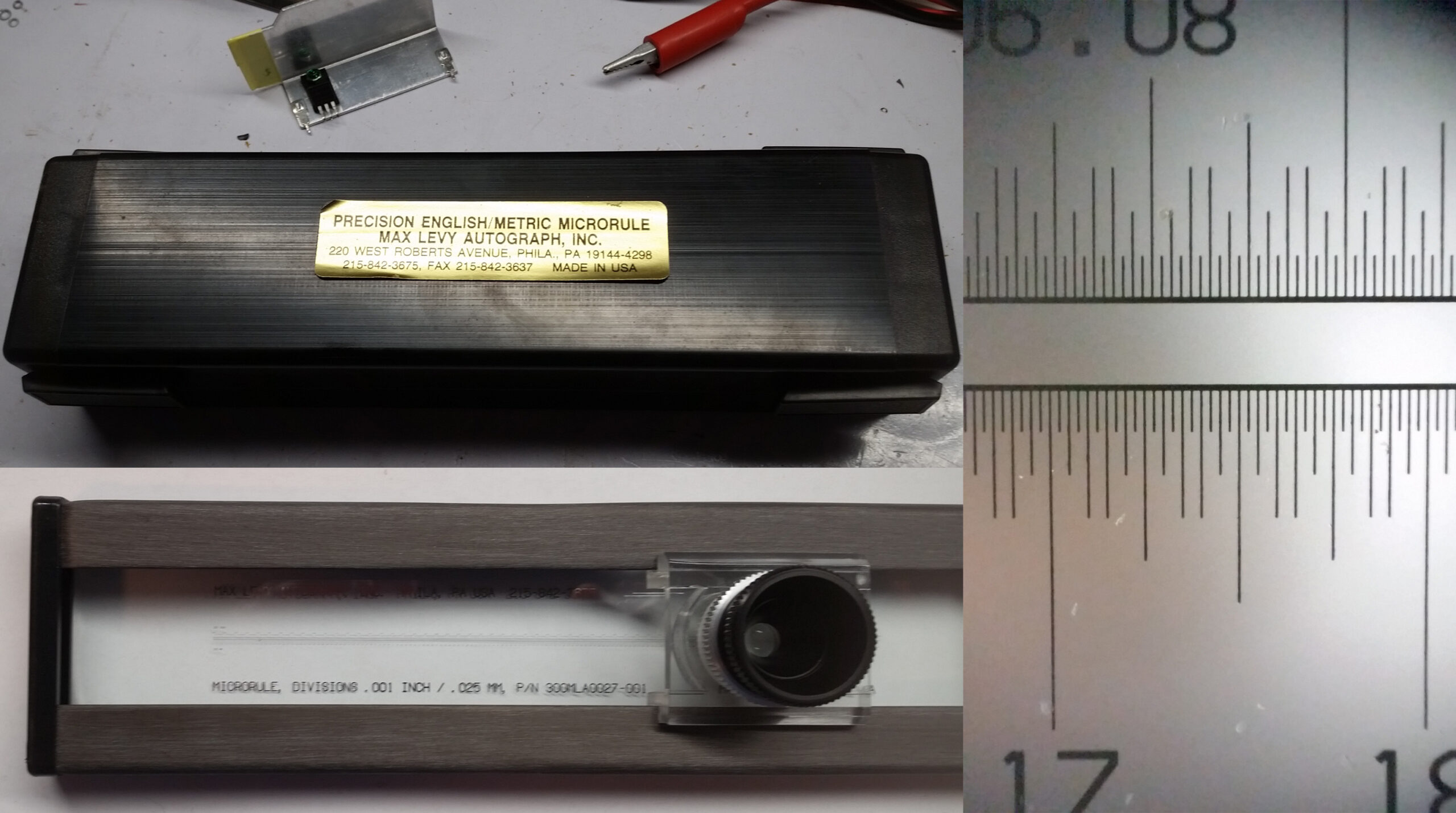
I had some very stringent contracts which required verification for certain dimensional relationships. Sometimes it was easier to whip this puppy out than set up the optical comparitor for reflective mode. Also, This was small enough for me to purchase personally as opposed to a $20k Nikon optical comparitor.
The Autograph uses chemically etched chrome legends on a 5.6mm thick soda-lime stabilized glass substrate, though they do not state the coefficient of expansion with temp.
I know the discussion was about masking and nm of line width, but this tool allows visual verification of ~0.01 mm (10 um) reliably over 6". It has come in very handy as my eyesight degrades over time.
So much for relevant content...lolol
Cheers,
Howie
A for effort Howie. I could joke how I've been wondering why some of the more extreme TT designers haven't gone to hydrostatic bearings for the platter (allusions to some/a lot of precision instruments), but I digress. We'll get back to cables or the fact that people are deaf/imagining things/misguided in some fashion/etc soon enough.
I could joke how I've been wondering why some of the more extreme TT designers haven't gone to hydrostatic bearings for the platter (allusions to some/a lot of precision instruments), but I digress. We'll get back to cables or the fact that people are deaf/imagining things/misguided in some fashion/etc soon enough.LOL, indeed!
I say bring on the precision measuring instruments! Supposedly we are here to share and learn about how to make better equipment, and no one does it merely by eye or ear and sensory augmentation is basically a super power...let's see what y'all have!
I have been using my QA400 for a while but not happy with the death of development for it as well as the lack of an ASIO driver for it, so I am working on an alternative approach. After that experience I won't spend money with QA again. I donna have the budget for an AP, but think I can come close with other systems.
My current plan is to utilize an RME ADI-2 Pro FS along with the Linear Audio Autoranger II. This system outperforms, but costs about the same as a 30-year old AP System One, for which all support is dropped and which will only run the early versions of AP software, never mind not having an ASIO driver. I used an AP S1 for many years in my lab, and appreciate it for how well it works, but I not a fan of investing thousands in obsolete systems relying on software...
Onward into the fog...
Howie
Hi Ed,
Thanks for the link, In addition to being 2.5 times what I want to budget for the RME + AR setup, I doubt the Stanford plays well as an ASIO device in Windows, which is my primary software platform I am interested in getting data into.
Nice unit though!
Cheers,
Howie
Thanks for the link, In addition to being 2.5 times what I want to budget for the RME + AR setup, I doubt the Stanford plays well as an ASIO device in Windows, which is my primary software platform I am interested in getting data into.
Nice unit though!
Cheers,
Howie
Howie,
The cost is what you pay for it less the money you get back when you sell it, plus of course the cost of the money.
The SRS is an IBM PC inside, I believe, so you should be able to do more with it and port to and fro. But I don't really expect a more of the music industry ASIO protocol to be available.
I almost forgot, optical comparators often show up at local machinery auctions. The auctioneer is on friendly terms, so let me know if you really want an optical comparator!
Last edited:
A for effort Howie.
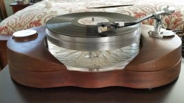
Of course they have. I can think of a couple of air bearing plattered TTs Air Force One - TechDAS High End Turntables 79kg of excess*
There was also one that used hydrostatic drive. Basically a plastic torque converter you put a record on.
*they did an even sillier model which came in at over 300kg.
Attachments
- Home
- Member Areas
- The Lounge
- The Black Hole......