In this instance that first input resistor is 150K and also a tiny parallel cap (a few pF) in parallel and a 20KHz flat o/p transformer becomes 100KHz flat. Without it, somewhere in-between.
BTW, the output impedance on the secondary is about 2.3 Ohm.
Yes, the frequency response limitations of an electron valve amplifier are linearly related to the output valves' driving impedance to the output transformer. DIY folk get workable amplifiers by just using triodes and no long loop feedback. Maybe not ideal, but buildable and predictable for non-professionals and home-brew.
I'd even submit that a well designed valve final stage amplifier, complete with an output transformer with all of its faults, is not unreasonable here in the closing days before the Rapture. But 2R3 is too big.
All good fortune,
Chris
Dadod, yes I know your amp that is the most impressive CFA I've seen.
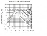
(Could-you provide the same curve at 1kHz ?)
i was not questioning-it, but the audibility of all those factors Richard was talking about.
BTW, why did not you choose laterals? For economic reasons ?
I was sure such a gentleman can't really exist in our actual world ;-)
I have a question about harmonic distortion levels at 20KHz. How could-we hear such frequencies ? May-be it is only the IM tat is more or less correlated ?
When I started this amp it was just for me and laterals are quite expensive (I needed six power amps to drive open baffle Orion loudspeakers). That is how all started, and Richard asks for two 200W version finished boards.
Damir
Maybe it would be interesting to propose a version with laterals ? The opportunity to compare performances and simplicity of design ?When I started this amp it was just for me and laterals are quite expensive (I needed six power amps to drive open baffle Orion loudspeakers). That is how all started, and Richard asks for two 200W version finished boards.
I take this opportunity to pay tribute to you, Ostripper and few others who will recognize themseves. Your curiosity and your creativity is exemplary and fruitful. Passion is refreshing and 'impertinence' keeps us young ;-)
I would like to thanks all the contributors that regularly encourage such explorations. They will recognize themselves as well.
It is still more pleasant to discover new landscapes at each walk than to do indoor sports on a treadmill under the control of a calorie counter ;-)
Even if, sometimes, the path does not lead exactly to the expected destination, the visit is always worth the effort.
Last edited:
Hi Damir,
Now that I am here, I intend to replace all the output devices with more rugged ones but the pin out is different. It has not been reliable enough to go anywhere with it. I will find out why/how the outputs keep blowing up. BUT...
When it is operating, the imaging layers, stability of the imaging and specific size and location is amazing and its best feature.
I attribute this to the fact that distortion does not change with Z load, freq or power level.
But, I never brought the amps to Calif to hear on my own familiar system. Now I need to get the JBL M2 speakers here with those amps. I have a new electronic cross-over bought for it so i can get rid of the amps from JBL.
I will be contacting Mark about shipping them in a month or two... Got to pay my taxes etc first. Property and income Ouch! I already spent $9500 USD to ship a few things over here. Those M2 are going to cost a lot, also. Takes about 3 months by boat.
I have a big screen acoustically treated video demo room to play them in. Right below my office.")
THx-RNMarsh
Hi Richard,
I was thinking what possible is the reason for blowing up output mosfet.
I have 100W version with PS regulator with integrated needed protection and sometimes, depends what preamp I use, the protection triggers and switch off the power amp. To prevent that I switch on the power amp the last.
I think as this amp is very fast that some high switch on transients from preamp could provoke overload of the amp and, in my case, trigger the PS regulator protection, but in the case od Richard 200W amp with not any protection built in, could blow the output mosfets.
I know that switch on power amp last is not good solution for commercial amp.
I would like to have some comments on this. I tried to avoid to integrate some crude protections in to amp as this, in most cases, to much increase distortion.
BR Damir
Just had a nice chat with JC, he points out the MOSFETs are not that robust. Attached is the data sheet chart for the 2SK1340.
At 70 volt rails I would expect current of at least 15 amps into a 4 ohm load. As loudspeaker's rated impedance is higher than the minimum, the current could go as high as 30 amps.
With 4 output devices this if truly shared equally wold be 7.5 amps,well outside of the safe operating area!
At 70 volt rails I would expect current of at least 15 amps into a 4 ohm load. As loudspeaker's rated impedance is higher than the minimum, the current could go as high as 30 amps.
With 4 output devices this if truly shared equally wold be 7.5 amps,well outside of the safe operating area!
Attachments
You really need to be making clear what type of mosfets you are talking about.
Trench mosfets (most modern switching mosfets use the technology) are designed for switching in things like solid state relays. If you switch them fast, they can conduct enormous currents - 100A in a TO220 quite achievable because of the low Rds(on). But, they have very limited SOA - a lot to do with their construction and thermal hotspotting. They handle inductive loads well without the necessity for flyback diodes because they simply avalanche on back EMF. for audio, the drain source body diode takes care of that though.
Laterals and verticals fare much better than trench devices with regard to SOA - and there's no secondary breakdown either.
I'd say Laterals are more rugged that bipolars - but I'm not a fan of the low gm and they're not as linear as bipolars. I guess you have to pick your poison and then learn to deal with whatever tradeoffs you have.
(I'm just donning my asbestos fire suit ).
Trench mosfets (most modern switching mosfets use the technology) are designed for switching in things like solid state relays. If you switch them fast, they can conduct enormous currents - 100A in a TO220 quite achievable because of the low Rds(on). But, they have very limited SOA - a lot to do with their construction and thermal hotspotting. They handle inductive loads well without the necessity for flyback diodes because they simply avalanche on back EMF. for audio, the drain source body diode takes care of that though.
Laterals and verticals fare much better than trench devices with regard to SOA - and there's no secondary breakdown either.
I'd say Laterals are more rugged that bipolars - but I'm not a fan of the low gm and they're not as linear as bipolars. I guess you have to pick your poison and then learn to deal with whatever tradeoffs you have.
(I'm just donning my asbestos fire suit
).(I'm just donning my asbestos fire suit
Yo dissin' mi LME49830 drivn ol' skool Hitch Lats bro?
is not unreasonable here in the closing days before the Rapture.
Chris
My sentiments exactly.
Just had a nice chat with JC, he points out the MOSFETs are not that robust. Attached is the data sheet chart for the 2SK1340.
At 70 volt rails I would expect current of at least 15 amps into a 4 ohm load. As loudspeaker's rated impedance is higher than the minimum, the current could go as high as 30 amps.
With 4 output devices this if truly shared equally wold be 7.5 amps,well outside of the safe operating area!
Free lesson:
You are talking about an amplifier that is designed to deliver 450W/4ohm (60Vpeak, or 15A peak, into 4ohm). Indeed, because of the speaker reactive impedance and it's drop, such an amplifier should be ideally able to handle a 2ohm impedance, so a 30A load current or, as you say, 7.5A/device (for 4 output pairs).
Let's look at the power dissipations of such an amplifier:
- Maximum power into 4ohm load is Vpeak^2/(2*Rload)=450W
- Maximum power into 2ohm load is 900W
- Maximum power supply current for Rload=4ohm is 2*Vpeak/(PI*Rload)~10A
- Maximum power supply current for Rload=2ohm is about 20A
- Maximum power absorbed from the power supply for Rload=4ohm is 2*Vpeak^2/(PI*Rload)~600W
- Maximum power absorbed from the power supply for Rload=2ohm is about 1200W
- The maximum power dissipation for the output stage, for Rload=4ohm, is 2*Vpeak^2/(PI^2*Rload)=180W
- The maximum power dissipation for the output stage, for Rload=2ohm, is about 360W
- In all cases, the output stage maximum power dissipation occurs at an output peak voltage of 2*Vpeak/PI which is the same about 38V output, or 180W into 4 ohm or 360W into 2 ohm of output power (note this is about 1/3 of the maximum output power, as above, and recall Mr. Atkinson testing the thermal stability of his amps at about this level, for 1 hour).
For 4 pairs of output device (doesn't matter bipolar or MOSFET, energy conservation applies to both
) each device will have to dissipate 22.5W/45W worst case for 4ohm/2ohm load.Assume the amp is designed to handle 450W output power into 4ohm continuous (so called "RMS power", which is technically wrong, there's nothing like "RMS" when talking about power) and 900W into 2ohm transients, to cover for speaker load dips and phase angle.
Assume a heatsink with 0.15 C/W (which is actually about all you can do without forced cooling). 180W continuous dissipation (4ohm load) plus some 60W of stand by (bias) power dissipation will raise the heatsink temperature with about 36 degrees over the ambient, and reach (worse case, at 40 degrees ambient) some 76 degrees centigrades.
Now, between each transistor case and the heatsink at 76 degrees you have a thermal pad, which has at best some 0.6C/W thermal resistance. Since each transistor will dissipate (for a 4ohm load) 22W, the case will be at a temperature of about 13 degrees over the heatsink, which is some 90 degrees centigrades.
Finally, between the each transistor chip and it's case you have another thermal resistance of not less than 0.5C/W, so the chip temperature is another 13 degrees over the case temperature, reaching 103 degrees centigrades.
Super rugged bipolar devices like the MJL4302/MJL1381 from OnSemi have a maximum power dissipation of 240W which has to be derated by 1.84C/W above 25 degrees. This means that one such device will be able to dissipate, and 103 degrees chip temperature, a maximum power of 240-(103-25)*1.84~100W which is greater than the 23W maximum power dissipation as above.
Let's look at MOSFET devices. As mentioned above, the power dissipations will be exactly the same; the popular IRFP240/IRFP9240 pair has about the same thermal resistances as the bipolar pair (same case), so temperatures will be about the same (ignoring the fact that MOSFETs have to be optimally biased higher than bipolars, so more standby power dissipation). However, these devices have a maximum power dissipation of only 150W, but with a derating factor much better than bipolar, of 1.2C/W. By plugging these numbers as above, we get that the maximum power one of these devices will be able to carry is 150-(103-25)*1.2=56W. This is indeed significantly lower than the bipolar case described above, but still no problems to handle 23W each.
So the bottom line is so far that either 4 pairs of bipolar of MOSFET devices could in principle handle 450W/4ohm output. But don't forget all thermal resistances used above are super optimistic, almost theoretical values. In practice, I would use no less than 5 pairs for 450W/4ohm output power, ideally 6 pairs.
Ok, now take a look at the 2ohm load transient behaviour. All power dissipations are doubling in this case, but of course the temperatures won't double, since the 2ohm load is only transient. The critical condition is to avoid exceeding the maximum derated power, under transient conditions. The bipolar SOA will further lower this power under certain circumstances, but ignore it for the moment.
One of the bipolar devices will have to dissipate 45W instantaneous, which is still much lower than the 100W guaranteed by the power derating factor (100W), so no problems. However, a MOSFET is able to dissipate only 56W, and 45W is already dangerously close, although not out of the theoretical limit. Given the practical limitations, I would say that 4 pairs of MOSFETs for this design are definitely not enough, but 5 or 6 pairs are perfectly feasible.
Now, consider the SOA in bipolars. For these ultra rugged OnSemi devices, and this amplifier, SOA is no limitation. These devices can take almost 10A at Vce=Vpeak=60V for 10mSeconds transients, so 4 pairs will be ok for this amplifier.
Exercise: redo the above calculation for other bipolar pairs, like the 2SC5200/2SA1943. Hint: you will be probably surprised that these (same case) devices have a maximum power dissipation of only 150W and the same 1.8C/W power dissipation derating. Which makes them significantly worse than the MOSFETs above, due to the much higher power derating factor in bipolars! And, to add insult to injury, this time the bipolar SOA contribution can no longer be ignored!
As a result, if such an amplifier with 4 pairs of IRFP240/IRFP9240 may hardly survive a 2ohm transient load, the same amplifier with 2SC5200/2SA1943 doesn't have a chance in hell. Five or even better six pairs will do.
Conclusion of this long discussion: Your statement (and I suppose JCs) of "MOSFETs are not that robust" is in general flat wrong. The correct answer is hidden in the detail of what transistors we are talking about. While it may be true for the rugged OnSemi or Sanken devices, it may not be true for other (excellent) power devices as Toshiba's. The maximum power dissipation and the power derating coefficients are the keys for designing and sizing a Class AB output stage; bipolar SOA constraints are important, and I would not design an amplifier that approaches the SOA limits, either bipolar or MOSFET, that's in my opinion a disaster waiting to happen. The amplifier example you are suggesting is not practically viable with either bipolars (other than the OnSemi) or MOSFETs. One would need to increase the number of output pairs anyway, then the bipolar or MOSFET solutions are perfectly equivalent from a power/thermal/reability perspective.
You are welcomed.
P.S. 2SK1340 is a transistor that is ridiculous to be used in such a power amplifier. It has 100W maximum power dissipation, Icmax=5A and Vdsmax=900V
Last edited:
Beautifully worked out, but when I follow Damir's links for the 200W version it is usingthe following transistors:
2SK134C
2SJ49C,
These are 140V, 7A, 100w devices.
Semiconductor: 2SK134 (2SK 134) - SILICON N-CHANNEL MOSFET TRANSISTOR... - UK (GBP)
not trying to suggest buying from there, but it was the first useful google link I found
2SK134C
2SJ49C,
These are 140V, 7A, 100w devices.
Semiconductor: 2SK134 (2SK 134) - SILICON N-CHANNEL MOSFET TRANSISTOR... - UK (GBP)
not trying to suggest buying from there, but it was the first useful google link I found
MOSFET transistors are plenty reliable as the above calculations show. At under $2.00 in quantity 24 of them will get you 350 Watts and never break. Broken units are much more expensive in shipping and reputation compared to a few $ upfront. Nothing like a little overkill for DIY.
When I started this amp it was just for me and laterals are quite expensive (I needed six power amps to drive open baffle Orion loudspeakers). That is how all started, and Richard asks for two 200W version finished boards.
Damir
I do not understand anymore. The 2SK134C/2SJ49C would not be Laterals?Beautifully worked out, but when I follow Damir's links for the 200W version it is using the following transistors:
2SK134C
2SJ49C
I would consider all output power calculations worst case with something like 45 degrees phase angle.
I have a LTspice tool somewhere and it is amazing how quickly things get out of hand with inductive loads. I use 6 pairs x 250 watt devices for that very reason on my 240 watter
I have a LTspice tool somewhere and it is amazing how quickly things get out of hand with inductive loads. I use 6 pairs x 250 watt devices for that very reason on my 240 watter
Anybody knows (looking mostly for data, not opinions) what would be the absolute worst case (from a design perspective) for a speaker impedance? I have among others a pair of Infinity Kappa 100 "amp killers" that drop under 2ohm (actually, 1.8ohm) somewhere in the bass, but the phase angle is almost zero there. I've seen other such pathological (but great sounding) speakers so I concluded that, as a rule of thumb, designing for half the nominal impedance is covering the worse case (either low impedance module, or a large phase angle) although for most cases it is an overkill. Designing for both low module impedance and 45 degrees of phase angle is IMO a double overkill, in particular in DIY. With the notable exception of something like the Apogee Scintillas, which dip under 1ohm - I call these "coned shorts".
Last edited:
Apogee Acoustics Scintilla: Impedance a measurement of the true horror of the scintillas. You want to own them just to have an excuse to build a monster amp that can handle them (or is that just me?)
Of course the original full range was even worse
Bass Panel = 1.86 ohms
Midrange Ribbon = 0.14 ohms
Tweeter Ribbon = 0.88 ohms
From the factory the mids had a transformer, but meh, real men can driver that
Of course the original full range was even worse
Bass Panel = 1.86 ohms
Midrange Ribbon = 0.14 ohms
Tweeter Ribbon = 0.88 ohms
From the factory the mids had a transformer, but meh, real men can driver that
Free lesson:
You are welcomed.
P.S. 2SK1340 is a transistor that is ridiculous to be used in such a power amplifier. It has 100W maximum power dissipation, Icmax=5A and Vdsmax=900V
Thank you all. So. we are back to what i said in #31055 and 31059.
Exicon Lateral MOSFETS - Our Product Range
The dual device/package.
THx-RNMarsh
Last edited:
Would you please give links to examples where someone asked for a favor here on diyAudio, a favor which required a couple hours of effort, and you were the one who performed that favor? Please?Can anybody measure R/C/L and RF characteristic impedance of say 3m length of Cat5 wired as four parallel pairs (speaker cable) please ?.
- Status
- Not open for further replies.
- Home
- Member Areas
- The Lounge
- John Curl's Blowtorch preamplifier part III