IMO it has collaspsed a long time ago. The party is over. Burnt toast here...
THx-Richard
I wish you the best in your new digs, Richard, I hope the move is invigorating and look forward to hearing from you here !
Best regards,
Howie
Thank you.... and if you need some amps, power products, dac... what ever just email me with request.
rmarsh@calweb.com
-Richard
rmarsh@calweb.com
-Richard
I have tried many times with Ohm meters, they show open circuit.
I haven’t used a high voltage insulator tester though
George
I have heard of glowing orange ferrite beads having ground contact. (from a friend)
It depends on the material.
regards, Gerhard
I have heard of glowing orange ferrite beads having ground contact. (from a friend)
It depends on the material.
regards, Gerhard
In a properly matched RF system there will be no current flowing on the outside of the coax, just on the inside of the shield and outside surface of the inner conductor. When ice damages a broadcast antenna system and causes a severe mismatch, it can cause high common mode currents to flow. In these cases I have seen common mode chokes (which attenuate exterior coax shield currents) made using ferrite cores get hot enough to melt their plastic enclosures.
This is not due to their electrical conductivity though, just their resistance to induced flux.
Howie
This is not due to their electrical conductivity though, just their resistance to induced flux.
Howie
So you are saying there is some way to produce heat from flux modulation that does not involve electrons? It could mechanically generate heat but you are saying it's a resistance to the induced flux as though that is the only thing.
The problem here is that the induced choke voltage is on the imaginary axis, so there can't be any power flow unless there is something in the magnetic loop converting flux modulation back to the imaginary axis (so it can be converted to real axis EMF). In the case of speakers, that is the motion of the coil through the flux. In the case of induction stoves, it is the magnetic inductivity of the pot (magnetic inductivity corresponds to cartesian conductance).
In a magnetic material the skin depth does not have to be smaller than the part in order for it to heat up. Even then the heat output is still proportional to power input. So you just need a very high AC current. IIRC ferrite is sintered, so while it may not be conductive between grains, the grains themselves could be conductive enough to have significant eddy currents. Since they are physically small, the skin depth may exceed their size. This only means that their shunt inductance will be small, so there will be little apparent change in inductance of the core, just the presence of a shunt resistance.
Last edited:
In an ideal magnetic material there is no loss, but in practical ferrite materials, there is hysteresis loss as well as what you state, eddy current losses. Many MnZn ferrites (mix 31, 75) have relatively low bulk resistivities, mix 31 for example is specified at 3000 ohms per cm^3.
Cheers,
Howie
Cheers,
Howie
In a properly matched RF system there will be no current flowing on the outside of the coax, just on the inside of the shield and outside surface of the inner conductor.
Howie
That does not even depend on matching. You can have huge SWR on a coax and no current outside.
These beads were carrying DC power. Some ferrite mixes conduct.
regards, Gerhard
I have heard of glowing orange ferrite beads having ground contact. (from a friend)
It depends on the material.
Hi Gerhard.
Reading your later posts I have to make a delayed clarification, that I was referring to loudspeaker motor ferrite and I think we have to think of the environment (EC voltage, current, frequency range) that they operate into.
That said, thank you for the info on RF ferrites, your input has produced a welcome exchange of info among knowledgeable members.
George
That does not even depend on matching. You can have huge SWR on a coax and no current outside...
regards, Gerhard
So true! If you terminate a 50 Ω transmission system with a isolated resistive load other than 50 Ω you will have a mismatch but no common-mode shield current on the coax feedline. However, if you terminate a transmission system with a radiator/antenna which shows an impedance imbalance between the radiator and counterpoise, or two halves of a dipole at the frequency you are operating, you will have external shield common-mode currents. This will be due to the imbalance current seeking an alternative path. Perversely, this imbalanced load can be properly matched and show low SWR, but the power is not all being radiated by the antenna, some is being radiated by the feedline!
A common-mode choke is one of the most neglected tools in both amateur and broadcast radio.
Back to ferrite speaker magnets, I think,...
Cheers!
Howie
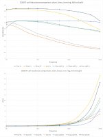
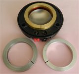
Finished the tests on the D205TI tweeter coil with brass, aluminum, and iron rings placed over the coil ID. The rings each were close to .250 inch thick, 2.05 +/- .002 inch ID.
Some really interesting results.
Top inductance scans.. as expected, the iron causes the system to have higher inductance, as it was a magnetic material, mu unknown. The top dark blue is the split iron ring, yellow is the full ring. Yellow is consistent with a front plate that is continuous and as a result, shows as a shorted turn. The dark blue, with the split, is no longer a shorted turn, and as is evident, inductance holds up better with frequency.
The orange is full aluminum ring, the grey is full brass ring. They both take a huge dive inductance wise starting from the getgo.
Also expected, the light blue and light green curves of the split aluminum and split brass do not dive as quickly inductance wise, as they no longer exclude field due to a shorted turn.
Of note, the split alum and brass do still show eddy losses, starting at 1000 hz. This is a consequence of a conductive material being brought into the time varying magnetic field, so it still reacts with eddy currents so as to exclude the field..hence lowering inductance.
The resistance is also interesting with a twist...
Yellow, full shorted turn iron ring, of course has the most dissipation, almost 2 ohms more at 20Khz. The iron split ring, dark blue, is better, roughly one ohm more than no ring at 20Khz. Indeed, cutting the iron ring halved the losses incurred by the ring.
What is really neat, is what happened to the aluminum and brass curves after they were split. above 20Khz, they exceeded the full ring dissipations. I expect that to be because with less field exclusion, more field was available to the bulk material as eddy generation loss. Given it's over 20Khz, I saw no reason to pursue this somewhat anomolous behavior.
From this data, specifically the iron full and split ring data, it would appear that breaking the circumferential conductivity of the faceplate will halve the shorted turn dissipative loss.
I also believe using a laminated faceplate structure will reduce the losses even further.
edit: second photo is tweeter with brass on it, iron front left, aluminum front right.
What these results suggest is the following...If one wishes to use a conductive ring as inductance control through xmax, the amount of inductance control can be tailored by the use of axial cuts in the structure. Not fully through the ring, but partials. By doing that, it will be possible to alter the behavior at higher frequencies, and dependent on voice coil position. (patent time again..)
jn
Attachments
Last edited:
can you show before and after ring cut on driver frequency response?
" " " " " " " " " " distortion?
-RNM
The ferrites which include iron powder mixed in are used for LF inductors. They can be conductive... often seen within a case or mold of insulated material.
I have very good success with ferrite formula #47. CM or DM coils for HF...... non conductive.
THx-RNMarsh
I have shown before and after Ls/Rs for aluminum, brass, and iron. All are cut, so "before" measurements are now moot. My current plan is to figure out how to rebuild the visiton driver to sweep it with a front plate gap.
Beyond that, dvc build, test for tap coil differential, and make a new voice coil two inches diameter two layer with two layer tap coil to do many tests to see eddy dissipation, Lenz exclusion, shorted turn...interesting stuff.
Timeframe unfortunately is beyond your move date... Hope it goes well, look forward to hearing from you after you are settled in.
Jn
What is really neat, is what happened to the aluminum and brass curves after they were split. above 20Khz, they exceeded the full ring dissipations. I expect that to be because with less field exclusion, more field was available to the bulk material as eddy generation loss. Given it's over 20Khz, I saw no reason to pursue this somewhat anomolous behavior.
jn
How much of the increase in resistance can be attributed to skin effect? I remember that was a component in LEAP's calculations for drivers. It also seems to be important for AC inductors operating in higher audio frequency range.
None, zero, nada. I have very carefully included measurements of the voice coil up to 100 kHz, and it is basically flat.
No skin effect at one fifth the max freq of my tests. Normally, I prefer two orders of magnitude over desired freq, but I believe a factor of five is sufficient here.
I present fundamental measurements... I find that many "embellishments" lack the fundamentals. That is why I have done these measurements.
Jn
Last edited:
...I present fundamental measurements... I find that many "embellishments" lack the fundamentals. That is why I have done these measurements.
Jn
Thank you...agreed +100...and did I mention thank you.
Howie

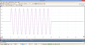
It is still useful to remember that measurement with sine-waves (you know single-tone or pure-tone) in the usual way (means using a distortion analyzer or voltmeter) is considered as so-called "steady state" measurement.
Is this considered a "steady state" measurement? You know, it uses a single-tone
.Attachments
- Status
- Not open for further replies.
- Home
- Member Areas
- The Lounge
- John Curl's Blowtorch preamplifier part III