You can experiment with decoupling cap types around DAC chip, each cap type sounds different as I am sure you knowThanks yet again, Markw4. I need to know the problem areas, if I am to address them. Of course, analog is relatively easy to 'improve' but it is not enough. Power supplies can be dealt with, but other digital based problems are a mystery to me.
") .
.IIRC Joe Rasmussen advocated Supercaps across DAC chip supplies.....they can contain carbon in the internal electrodes so this might be what is different in sound to other caps, I have not tried this.
PM me for other info if you like.
Dan.
Thanks, syn08 for your latest input. It is just the sort of info that I need.Thanks for the confirmation, 44 degrees phase margin, a disaster waiting to happen. And that's not even with the output close to the power rails.
For your education, given an N pole compensation schema (you are showing for N=2) there is still not much room to wiggle the ULGF while not affecting the stability margin. This is because audio amplifiers are by their nature minimum phase systems, therefore the magnitude and phase of the loop gain are not independent, you can get the phase(w) by simply applying a Hilbert transform to the gain(w). The only way to pull more loop gain from an audio amplifier, without pushing the ULGF to absurd values, is to use a higher order compensation network, a typical example would be the Cherry NDFL (which was practically used in the PGP amp). Or, in general, to use N poles followed by N-1 zeroes in the loop gain (to bring back the phase) and at the same time taking care of the sensitivity to stay within reasonable limits. I know of a couple of amplifier that are using N=5, one is an amazing small scale commercial class D amp, the other one was designed and build by a former member here (GK) as a proof of concept, but that one had other issues (was going berserk when approaching clipping).
And this is where the free lessons ends. For more, I can send you my hourly rate
BTW, there's no relationship between the gain/phase plots you are showing, it's like you are pulling rabbits from a hat. I'm sure you have more
Tricon MMIC website is still upI was surprised how far two people with nerve can get
("The details contained in the charging documents are allegations. The defendant is presumed innocent unless and until proven guilty beyond a reasonable doubt in a court of law.")
George
This proves your meager knowledge of electronics for having plunged into this fabric of nonsense and conjunctures. Of the same kind as those he has assaulted on the amp of Richard (Read his denial) and the design of Dadod (Who responded as appropriate) .Thanks, syn08 for your latest input. It is just the sort of info that I need.
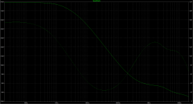
He claims that it is impossible to make an amp with ULGF> 6MHz? This one goes up to 10.
He claims that the phase margin is 44 °, that he gets out of his hat, while it never goes below 91.4 °.
He makes conjectures about the rail voltage, of which he does not know the level.
He says some stupidity about how to measure the slew rate and do not even understud my answer.
Slew rate have to be measured clipping the amp and calculated between 10 and 90% of the total excusion.
The simple fact that there is no bump of the response curve at the end of the band and no overshoot on square signals should have reassured you about the stability of this amp that gives good and loyal service for more than three years now and supported high capacitive loads on the bench. No need for a Tian simulation of OLG.
Not to mention what he claims on my models, old classic, which are the Cordel ones, the best available for my devices as far as I know. Wrong again.
Funny too his conjunctures about the type of compensation i used, knowing nothing about my schematic.
Fake is fashionable.
This said, my real amp in real life had been more compensated after the tests and measurements, no need for overkill.
And, as appropriate, HF incoming signals are filtered far below its capabilities.
BTW: It sounds very smooth ;-)
Last edited:
You can experiment with decoupling cap types around DAC chip, each cap type sounds different as I am sure you know
IIRC Joe Rasmussen advocated Supercaps across DAC chip supplies.....they can contain carbon in the internal electrodes so this might be what is different in sound to other caps, I have not tried this...
Dan, try it.
Seems that supercaps keeps out ultra-LF noise on the DAC that makes them sound more 'digital' and especially with delta-sigma DACs. Having been doing this for about ten years (late noughties), passed it on to some of the DAC designers like clayton Gieseler and also discussed this on the Oppo upgrade thread. Now using supercaps has become a lot more common, they are popping up all over the place.
Also, put one also on the +3.3V to the oscillator where PS is ultra critical.
Above is so easy to do, no reason not to try it.
Joe
"No amp on the market" syn08 seems not to have a lot of experience with CFAs.
PGP Amplifier
Author | Linear Audio
<snip>
Slew rate have to be measured clipping the amp and calculated between 10 and 90% of the total excusion.
Usually, the slew rate is measured by a square wave or step input signal that forces the amplifier to slew (a condition we would never like to see during normal operation) and then the maximum rate of change at the output is measured.
Of course, it is a large scale parameter but there is no need to drive the amplifier into clipping.
Yes, I was making an educated guess, and I guess your guess is as good as my guess at this stage. I'm sorry if I upset you Richard and I apologize for the trouble.
P.S. Bob Cordell just posted this today, quite on topic I would think. You may find Bob Cordell more trustful than yours truly.
https://www.diyaudio.com/forums/sol...lls-power-amplifier-book-939.html#post5826115
I followed your work and I have high esteem of your knowledge, but what bother me is a way you make a comments(attacks?). Why you don't allow that an amp of higher ULGF then used in standard commercial can be very stable. In my opinion Cordell is quite conservative in that respect.
I agree dadod, I have an amp with LG as attached and it is stable with no problems.
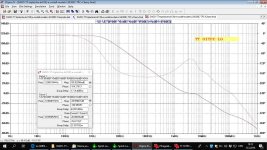
Are my eyes bad, or the ULGF is 700KHz in this example?
This proves your meager knowledge of electronics <snip>
Straight to /dev/nul
Are my eyes bad, or the ULGF is 700KHz in this example?
You are correct of course. A small mod (cap value) makes ULGF = 2MHz but I keep it 700kHz for reliability reason.
Simulations - take care. This one is with BC models of 21194/3 and LTSpice and seems to be close to reality. With standard models in MC simulator ULGF gets higher but all audio parameters seem to be closer to reality with Bob's models in LT.
Dan, try it.
Seems that supercaps keeps out ultra-LF noise on the DAC that makes them sound more 'digital' and especially with delta-sigma DACs. Having been doing this for about ten years (late noughties), passed it on to some of the DAC designers like clayton Gieseler and also discussed this on the Oppo upgrade thread. Now using supercaps has become a lot more common, they are popping up all over the place.
Also, put one also on the +3.3V to the oscillator where PS is ultra critical.
Above is so easy to do, no reason not to try it.
Joe
Why would you use a high ESR supercap on a supply very easily taken care of with actual low noise regulators or reference circuits?
You are correct of course. A small mod (cap value) makes ULGF = 2MHz but I keep it 700kHz for reliability reason.
Which is of course a sensible thing to do, and precisely the point that Dadod seems to miss.
Anything is possible in simulation, but in practice is not that easy...
Only problem I have is your attitude and assuming you know what the answere is. It is not oscillating.
Appears to be heat sink to mounting plate interface is not thermally coupling good enough and I asked them to fix it.
This is a hint. Please check heatsink grounding/connection to AGND. Usual trouble is when a floating heatsink through its capacitance to power transistors case makes the amp oscillating. It may have been OK in a prototype where you have it under control. This is an issue especially with fast designs.
You are correct of course. A small mod (cap value) makes ULGF = 2MHz but I keep it 700kHz for reliability reason.
Simulations - take care. This one is with BC models of 21194/3 and LTSpice and seems to be close to reality. With standard models in MC simulator ULGF gets higher but all audio parameters seem to be closer to reality with Bob's models in LT.
Pavel, this is very strange way to agree with me?
Only problem I have is your attitude and assuming you know what the answere is. It is not oscillating.
Appears to be heat sink to mounting plate interface is not thermally coupling good enough and I asked them to fix it. Other could be reversed diodes used for protection.... they are checking on that possibility. DaDod alerted me about that possibility.
I am sure, we will find the cause and be back on tract soon.
THx-RNMarsh
Surely a high end amplifier in 2019 would include an MCU to monitor output device temperature and other fault conditions?
Pavel, this is very strange way to agree with me?
I hope not. My point is that it is possible to manage loopgain effectively by the compensation method used and I think we both agree on this. The ULFG reduction - higher margin may prevent from unexpected situations in a manufacture process. I think that possible raise of distortion from 0.0002% to 0.0004% (example only) is unimportant compared to higher reliability margin.
I hope not. My point is that it is possible to manage loopgain effectively by the compensation method used and I think we both agree on this. The ULFG reduction - higher margin may prevent from unexpected situations in a manufacture process. I think that possible raise of distortion from 0.0002% to 0.0004% (example only) is unimportant compared to higher reliability margin.
200W CFA that was built for Richard has very high margins PM=85 degree, GM = 21 dB (simulated of course, I don't have means to measure it in real amp). Lowering ULGF will not improve it much.
One of the reason I chose mosfet OPS is possibility to use fast drivers as KSA1381/KSC3503 (or even with no drivers at all) and get less phase shift and higher ULGF.
Even in my ThermalTrak VFA with triple OPS I switched to OITPC and get ULGF of 3.2 MHz, still working for some years with not problem what so ever.
Attachments
- Status
- Not open for further replies.
- Home
- Member Areas
- The Lounge
- John Curl's Blowtorch preamplifier part III