If you're looking to reduce OLG by tinkering with external components only, Sergio Franco's book (link to inexpensive paperback edition) presents an excellent circuit approach, in Figure 8.24 (p.375) of the Third Edition. To find it in other editions, go to the chapter on "Stability" (ch.8) and find the section on "External Frequency Compensation" (sec. 8.4). There it is.
BTW I doubt that this is truly "the best" way. I'm sure there are company proprietary trade secrets that cannot be mentioned here, which are even more bester.
That's the kind of approach I was alluding to in my earlier approach. Thanks for posting.
Cordell has shown that if loop gain is adequate, Phase Intermodulation distortion is negligible on a typical Miller comp'd amplifier - often the reason cited here for eschewing IC opamps and going discrete.
I don't use MC on power amps because usually I want to maximize loop gain at HF to ensure 20k distortion is low. TPC TMC and OIC schemes were not really mainstream until 10 or 15 years ago so I suspect this is the main reason why most (not all) commercial amps up until that time were MC'd - people just didn't know about other comp options. As usual the semi industry was ahead of the curve because Robert Dobkin (Natsemi)published his TPC Linear Brief in the late 1960's or 1970.
If you look at the e-Amp write up on my website I show the loop gain plots for various comp schemes - you can jumper select them on the amp. I also had the option ot load the VAS to lower the overall loo pgain, but extend it to c. 40 kHz (IIRC - long time since I looked at it - but it was pretty wide band).
For small signal stuff, I think MC makes very good sense.
Last edited:
Let us try to understand what is really happening when we 'allow' some lower order harmonic distortion (2,3) to be generated at the output of an audio design.
Not everybody likes to use fully complementary circuitry like I do. Some very good designs use a single ended (usually n channel jfets almost exclusively at the input or tubes) designs and they can sound darn good. However they will have much more 2'nd harmonic than 3'rd. This is because they will follow the laws of physics that are intrinsic to tubes, fets, or transistors, and not have any mechanism to naturally cancel the even order (2'nd, 4th etc) harmonics and 2'nd is always the dominant nonlinearity of ANY active device in Class A operation.
This aside, let's say that we want to use solid state, but complementary balanced through-out? Then, we have a useful mechanism of cancelling virtually all the even order distortion, but in general, we will find that we will not get a PERFECT cancellation because of device matching both intrinsic and extrinsic. i.e. Pchannel devices are always somewhat different from Nchannel devices, for example. The usual way to get perfect cancellation is to actually add a trim pot somewhere to force the complementary gains to match and therefore cancel. Is this important? Probably not, as much as we used to think. But the practical result is some 2'nd and some 3'rd harmonic that can be measured, even at normal operating levels, unless you use many 1000's of times (you know, 60dB or more) negative feedback to reduce the inherent open loop distortion to virtually nothing left to measure.
Now what is wrong with that? (as Scott might say) Well there is always a tradeoff between open loop bandwidth and the amount of maximum feedback that you can use.
Normally, (there are some exceptions with other problems) a circuit thought to be a successful op amp will have an open loop bandwidth of just a few hundred cycles or much less. This is an open invitation to generate PIM distortion, as is known by researchers, and many audio designers, including me, have found that higher open loop bandwidth is better than low open loop bandwidth, subjectively, when comparing IC op amps and discrete op amps as well. So what do you do, if you are designing the BEST discrete op amp that you can? Do you go for really high feedback, with its attendant LOW open loop bandwidth? Or do you try to raise the open loop bandwidth as much as possible, even if you can then measure some residual 2'nd and 3'rd harmonic especially at higher operating levels, because you have thrown away some feedback? Only subjective listening tests can tell you which way to go. The headphone amp that we recently discussed has control of how much distortion he can allow, before it becomes eminently audible, but at the same time lowering potential PIM (or whatever we hear) when open loop bandwidth is increased significantly. This is a control used by Matti Otala back in 1973, me, and just about any serious audio designer of discrete amps.
If you're looking to reduce OLG by tinkering with external components only, Sergio Franco's book (link to inexpensive paperback edition) presents an excellent circuit approach, in Figure 8.24 (p.375) of the Third Edition. To find it in other editions, go to the chapter on "Stability" (ch.8) and find the section on "External Frequency Compensation" (sec. 8.4). There it is.
BTW I doubt that this is truly "the best" way. I'm sure there are company proprietary trade secrets that cannot be mentioned here, which are even more bester.
I have a slightly different set of audio design criteria than Scott and industry for line level audio. It always sounds and measures great so i keep using it.
Low to moderate GNFB. Low to moderate CLG. High OLG BW. High SR. Lowish noise. Complimentary push-pull topology (generally, CFA). Extreamly low distortions.
How to do that easily with a high OLG IC Opamp? Do it with the IC and buffer IC mentioned and what do you get for distortion?
THx-RNMarsh
Last edited:
Its very easy on a power amp to have wide loop bandwidths - that's what TPC, TMC etc are all about. And its also very easy to adjust the loop gain magnitude as well, if that is a concern you have.
If you want that on your op-amp based designs then there are a number of routes you can go if you have access to the comp pins.
But, I can honestly say in the many, many preamps and amps I've heard, I would not be able to say that any specific amplifier category (IC, discrete or tube ) was consistently better than another.
What usually separates good sounding gear from the rest is attention to all the things that can possibly impact on the performance - like layout, decoupling, stability, PSU design.
Richard, dadod's amp is high GNFB - not low GNFB (80 dB IIRC).
Sorry, I don't buy the PIM thing. If it exists to any extent in a modern opamp, its more than 6 orders of magnitude below the fundamental. Where is it? I've never seen a plot of this even though the mechanism can be described (Cordell)
Last edited:
I have a slightly different set of audio design criteria than Scott and industry for line level audio. It always sounds and measures great so i keep using it.
Low to moderate GNFB. Low to moderate CLG. High OLG BW. High SR. Lowish noise. Complimentary push-pull topology (generally, CFA). Extreamly low distortions.
How to do that easily with a high OLG IC Opamp? Do it with the IC and buffer IC mentioned and what do you get for distortion?
THx-RNMarsh
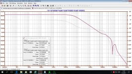
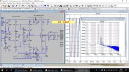
Preamp GainWire mk4 with IC buffer and discrete current conveyor IPS showed some post back Loop Gain plot is here. CLG is 11dB.
edit:
It's easy to lower LG to 30dB flat up to 90kHz and THD is still very very low.
Attachments
Last edited:
I asked you before, did you actually read Ron's paper? He found, like Bob, no PIM in IC's on modern processes unless they simply were designed to run on uA (not for audio).Try harder to understand PIM.
Ron's tests are still primitive, as he has to design his own test equipment in his garage. IF an upscale audio test equipment manufacturer would design this test into their test equipment, we would most probably have a much lower distortion residual, and therefore virtually every IC could be measured easily. Of course, it might be that PIM as defined by Otala is again not the only mechanism detected by the human ear when it comes to how much feedback one uses.
Try harder to understand PIM. There are several AES papers that go much farther then Bob Cordell did, back 35+ years ago.
John, you are doing it again. You keep harking back ‘35 years ago’ like your LM741 thing. Modern opamps are about as close to a 741 as a WW1 bi- plane is to a F35.
Wrapping amplifier design up in subjective mystique and peddling it as ‘advanced engineering’ is just nonsense and you know it.
Where is the PIM plot on a modern opamp? Please produce a valid measurement otherwise this is just another straw man.
Normally, (there are some exceptions with other problems) a circuit thought to be a successful op amp will have an open loop bandwidth of just a few hundred cycles or much less. This is an open invitation to generate PIM distortion, as is known by researchers, and many audio designers, including me, have found that higher open loop bandwidth is better than low open loop bandwidth, subjectively, when comparing IC op amps and discrete op amps as well. So what do you do, if you are designing the BEST discrete op amp that you can? Do you go for really high feedback, with its attendant LOW open loop bandwidth? Or do you try to raise the open loop bandwidth as much as possible, even if you can then measure some residual 2'nd and 3'rd harmonic especially at higher operating levels, because you have thrown away some feedback? Only subjective listening tests can tell you which way to go. The headphone amp that we recently discussed has control of how much distortion he can allow, before it becomes eminently audible, but at the same time lowering potential PIM (or whatever we hear) when open loop bandwidth is increased significantly. This is a control used by Matti Otala back in 1973, me, and just about any serious audio designer of discrete amps.
I have a slightly different set of audio design criteria than Scott and industry for line level audio. It always sounds and measures great so i keep using it.
Low to moderate GNFB. Low to moderate CLG. High OLG BW. High SR. Lowish noise. Complimentary push-pull topology (generally, CFA). Extreamly low distortions.
How to do that easily with a high OLG IC Opamp? Do it with the IC and buffer IC mentioned and what do you get for distortion?
The same old stuff, packaged in the same old "high end audio" context.
The fact that these legends were debunked ad nauseam is, of course, irrelevant. Every attempt to invoke the laws of physics, the EE body of knowledge, any STEM based rationale, will be countered with the "I know what I hear", "trust your ears", "because I am a famous designer", bludgeon arguments. A war that can't be won.
You keep harking back ‘35 years ago’
Wrong, it's more like 50 today, some things never die.
I'll go with what I hear, thank you. I never used a 741 except for control servos back in 1969. They worked pretty good for that. By 1970, I was using Harris HA-911 op amps with almost 10 times higher slew rate. Richard Burwen found the same IC and used it with the original Levinson LNP-2 preamp. Later, we designed even the HA-911 out for faster and more open loop bandwidth discrete designs. More trouble, but worth it sonically.
 .
.
Last edited:
Dadod's amp looks ideal for open loop bandwidth.
I could apply a little positive feedback via input offset and make the OLG 100dB and guess what, nothing would change.
Is it just your preference or do you compare with natural sounds for accuracy like Richard says he does?Trust your ears, they are what counts, not specs.
A few years back I have seen a closed loop residual slight increase of H2 and decrease of H3 on introduction of local drain to gate feedback on a mosfet VAS, measured at 1W output. The difference in proportion of residual H2/H3 may have some contribution to the audible difference.... it might be that PIM as defined by Otala is again not the only mechanism detected by the human ear when it comes to how much feedback one uses.
Yes, but easier for others to understand and verify measured quantities.Trust your ears, they are what counts, not specs.
I strongly suspect that you will find a difference once you take a closer look at your measurement, especially on multitone signal.Nothing that YOU MEASURE would change, perhaps.
Last edited:
- Status
- Not open for further replies.
- Home
- Member Areas
- The Lounge
- John Curl's Blowtorch preamplifier part III