Right, but...It would be nice if the real world system non-linear transfer function was only polynomial and independent of frequency. Nice basic lecture for students, however.
The causes of speaker distortion are twofold. Theoretical, inherent in the system and those, practical, dependent on the manufacture. Improving the second does not prevent to study the first and take countermeasures: any reduction of distortion is good to take, don't you think ?
Last edited:
I agree, I think I was clear enough when mentioning that as an essential introductory lecture for beginners students the document is fine. On the other hand, I believe that many of us are above that stage, so the document is not what we are supposed to learn and study ") .
.
.Which raises the question where the "3db" came from?
While i usually agree that any kind of model use should be taken with (at least) a grain of salt, we already knew from the informations linked and posted about this topic in the recent days/weeks that in a condenser (brüel&kjaer for example) mic of the standard construction H2 is the dominant distortion component in the weekly nonlinear region.
From the measurements published by Erling Frederiksen (and the two thesisesis ) it that taylor series approximation is appropriate for these microphones, furthermore the publications show that there is quite good agreement between calculated and measured performance in this region.
At higher frequencies and higher pressure levels and if different constructions came into play, things obviously get a bit more difficult.
Edit: Initially i answered a question from 1audio about the usefullness of the difference frequency measurement approach and it was my understanding that he uses microphones/impedance converters and measurement amplifiers that are working according to the assumptions for this model approach....
Last edited:
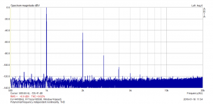
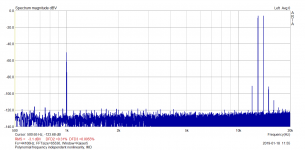
Attached are measurements taken on a system with polynomial, frequency independent non-linearity. It is a harmonic distortion at 1kHz and twin-tone CCIF IMD distortion 13+14kHz, with difference tone (H2) of 1kHz. Both signals have same peak amplitude. This means, 13+14kHz rms value is -3dB compared to the 1kHz tone and each of the 13, 14kHz tones have amplitude -6dB compared to 1kHz amplitude. Harmonic and IM distortion components are easily readable from plots. This might stop the discussion on IM x HD, I hope, but remember that the result is only valid for a polynomial frequency independent non-linearity. One can see that the relative H2 component with respect to amplitude of the single tone is the same in both cases, taking into account that IM signal components are -6dB of the 1kHz test tone. Distortion doubles with double amplitude.
Attachments
Last edited:
OK.
I think we can agree that a condenser mic like from B&K ($$$) can be used to measure the typically much higher HD of dynamic drivers.
And, that you can also use certain inexpensive electret mic as well as long as the max SPL at the electret is not more than 90 dB.
Now we need to get back to modifications to typical, basic dynamic driver design that will lower the distortion when driven hard enough to produce SPL of 80-90 dB at the listening distance.
THx-RNMarsh
Last edited:
Seems to be sort of talking past each other / misunderstanding.
The before mentioned conclusion from the taylor series for the difference frequency method isn´t related to the HD2 from an excitation at the difference frequency but to the HD2 component from each of the two excitation signals (in case of the afore mentioned closely spaced frequencies).
So if you use 1000 Hz and 1070Hz as input signals (same amplitude) then the level of the IM2 component at 70 Hz should be 6dB higher than the level of the H2 component at 2000 Hz or 2140 Hz.
This means, 13+14kHz rms value is -3dB compared to the 1kHz tone
Should this be: ?
This means, 14-13kHz rms value is -3dB compared to the 1kHz tone 2nd Harmonic
George
PMA, the lecture notes by Meyer were primarily meant for Richard. He, like many others here, never took that specific course. This is the EASIEST and clearest way to present this material, AND it can be very valuable 95% of the time, with clear ratios between distortions noted, etc.
If you want the textbook built from these notes, then we have to go to another book by Dr. Don O. Pederson, "Analog Integrated Circuits for Communication' for the more hard to read version. And of course, on to the Volterra series. '-)
If you want the textbook built from these notes, then we have to go to another book by Dr. Don O. Pederson, "Analog Integrated Circuits for Communication' for the more hard to read version. And of course, on to the Volterra series. '-)
I did not and still dont want to go back to the stone age of math to find out what the THD of a mic is compared to a dynamic loudspeaker. As almost interesting and exciting the derivations and theory is in mic cal etc.... I just need to know the bottom line to know if I can use a mic in this speaker mod/HD app. Which are good enough for the App?
Just that there have been ways to measure the mic distortion and it has been done and the results are ---- that the cap mic is very much lower than the DUT (spkr) is good enough for now.
That alone is enough assurance. Then at lower cost but limited spl/dynamic range is the electret cap mic... also has been measured and is also useful for the purpose.
What more is needed to know to proceed?
THx-RNMarsh
Last edited:
Hi Richard, I hope you are not referring to the pages that I scanned especially for you, but valuable for anyone else who wants to get a good working set of relationships with both the nature of harmonic and IM distortion. This is the easiest and clearest presentation that I have ever encountered, and it is valuable in that you can then easily predict distortion levels, once you get a single measurement at higher and lower amplitudes.
Today, we have become very lazy, using SPICE, etc for our calculations, but there is method in these measurements that predict well. PMA is just showing that he is better educated as an engineer than most of us, so he dismisses it. I am surprised the JN has not yet impugned the professor who wrote these notes, since he has put down just about every other professor that I have cited over the last 15 years. '-)
Today, we have become very lazy, using SPICE, etc for our calculations, but there is method in these measurements that predict well. PMA is just showing that he is better educated as an engineer than most of us, so he dismisses it. I am surprised the JN has not yet impugned the professor who wrote these notes, since he has put down just about every other professor that I have cited over the last 15 years. '-)
No its fine John. Just it is past the point of need to have my answer.
yes, it is true, SPICE etc and math solver software etc has it all canned now. Which has good and bad sides.
THx-Richard
Truer words were never spoken in this day and age of the Internet.
It would appear that you have read Asimov's "The Profession".
This is a daily fight at work, constantly trying to get the young ones to look beyond their computer screens and understand the system they are trying to control.
Oh, also.... Increasing the BL at the excursion limits to overcome increasing suspension forces cannot work to decrease distortion. Yes, as the suspension tightens up we could ingrease "gain" to compensate, but that is a position based gain and not a direction based. Once the motion stops and reverses, the increased gain would add to the suspension restoring forces.
Problem is, the magnetic gain is current (and therefore acceleration) based, while suspension forces are position based (second integral).
Jn
JN thanks for the hint about 'the Profession' I read the summary and could not agree more.
As far as the lecture notes are concerned: They ARE old. In fact the professor (Meyer) that I cited is slightly younger than me and is already retired from UCB. He still is active, however, I am told.
The POINT of the lecture notes is looking at the SIMPLE mathematical relationships between specific harmonic distortions with level. For example 2'nd harmonic always rises linearly with level, while 3'rd harmonic always rises with the SQUARE of the level. This implies that it is almost impossible to get reduce 2'nd harmonic to zero, unless you deliberately null it out. It also says that 3'rd harmonic, once it reaches approximately the level of second harmonic, will always race ahead and dominate with increasing output. These are good to know 'rules of thumb' that inform you as you measure.
IM is also related to each harmonic in a relatively simple way, AND there is yet another IM product, that is larger than all the other IM artifacts called the 'TRIPLE BEAT' that might cause wonder if not known about. etc. I hope that this helps some of you out there.
Kinda remnds me of when -on another forum - we were making an oscillator --- I could vary the 2H and 3H levels but they were always in opposition... If 2H increased, 3H decreased and visa-versa. Fun to watch as I adjusted a trimmer.
BUT --- so what.... I just set it so 2H=3H in amplitude and forget about it because both were in the -140 dbv region!
So, I dont know that any of this matters to me. My friend, Robert Green from UCLA (math professor) had same discussion with me about his students preferred to use the software to solve equations without the derived details. I am afraid in most cases i am one of them. Because applied science is the name of the game and end results matter and our time on earth is limited.
Unless, it helps to get us a more linear speaker, then I dont want to spend time on it. So, lets move on and learn from ideas and concepts like i had... leap-frog me ... what magnet structure would help better?
Or which combination of winding geometry and variable density along with varying mag field density can produce a more linear total affect when combined with the suspension's affects?
Is this the best group to ask such questions? I am also interested in reducing the total music system's group delay and how to measure it. And correct it.
THx-RNMarsh
Last edited:
Be reasonable! Do it my way.
OK If your way works by getting results towards the goal. Whats your way?
-RNM
Last edited:
From the questions that I read here previously on both microphones and distortion in general, a little study would SAVE TIME. Let us not rationalize that we don't need to study up too much.
john. it just is not needed in order to know if a mic will be suitable or not for this app.
Geez.
What would save time is some distortion mic data. but thats finally been done/found now. so why are you still going on in ever greater detail? Taylor series etal. Now, if we were designing the capsule and its preamp to lowest thd/IM as possible, it could be helpful to know. but, we are not. At least I am not.
-RM
Last edited:
From here it seemed like the point was that everyone thinks their way is reasonable.
Hey Mark. can you come over tomorrow?
-RM
- Status
- Not open for further replies.
- Home
- Member Areas
- The Lounge
- John Curl's Blowtorch preamplifier part III