I didn't have a nonlinear model for the inductors. It could perhaps be made with the Chan model in LTspice. We would need an Le(I) plot and a hysteresis plot. If I had found one I might have already done it.
Le(x) is easier to model I think if you can figure out how to do it without causing problems for the matrix solver in the simulator.
Le(x) is easier to model I think if you can figure out how to do it without causing problems for the matrix solver in the simulator.
Yes, just like current drive which is very similar though not identical in the fine-print. It has the same basic advantages and limitations.But does the scheme really lower the distortion?
@Keantokens sim is spot on, in my view. It shows that isolating the true Re voltage really works when coils are matched in BL and see the same 3D flux environment, plus the (hopefully) close coupling of the parasitic Le of the coils eliminates any (distorted) voltage accross Le itself, so really the true and only Re voltage is isolated, on which the control loop then works upon... giving constant current (apart from thermal drift).
And as with current drive some degenation at Fs seems appropriate, normally derived from terminal voltage but another signal like (extracted) velocity could be used as well.
For a given SPL target the terminal voltage, the Re voltage and the velocity voltage always look the same, respectively, no matter on which entity we regulate upon to get to that target. To arrive at the best distortion, SNR, stability and large signal robustness, overall, we may regulate on either the terminal voltage (standard voltage drive), the current (indirect or direct) or the velocity (if properly extracted), actually blend between sources (even vs. frequency) used for feedback. Finding out what works best is the hard part, of course.
We could even take it one step further and apply an outer control loop on top of this, for example regulating on the SPL picked up by a close mike and/or the signal of a truly indendent sensor (eg velocity).
The amp-speaker interface has many more degrees of freedom than plain voltage drive which might be exploited to better a given driver significantly, at least that's what we all hope.
Last edited:
I give a daffynition....Circular currents of the plate and eddy currents in the plate are one and the same.
Eddy currents are the circular (better: circulating) currents
")
Definition: Circular current: current which globally moves in a specific circle. For example, if you take a ring of copper, and place it through a toroid, it will act as a shorted secondary because it is. Amperes of current can flow, and it will create a solenoidal magnetic field. When that field collapses, it will return energy to the coils of the primary.
Eddy currents. They are infinitesimal circles of currents within a conductive object around flux lines that are changing in intensity. The magnetic field the whorls generate fight the rate of change of the driving flux rate of change. When you put a copper sheet into a changing magnetic field, it does not store global energy so cannot return it.
While the pure mathematics do not entirely agree with my simple summation, I have provided the practical and testable reality that we worry about.
If you were to cut out the last 1/4 inch of the front plate to form a ring, and place that ring over a voice coil which is carrying AC current, there will be current flowing in that ring in a circular fashion. The current will be circumferential.
If you move the ring along the energized coil, the flux lines will generate vortices of current (eddies) which are circular with respect to the radial direction. IOW, if you were at the center of the vc and were looking at the inner surface of the ring of faceplate, you would see circular currents which are on the face of the surface you are looking at.(target #1)
The second pdf you posted is just too funny. Last year, I got a call from the vacuum group...the problem was we have 1/4 inch thick alumina beam pipes with a titanium sputtered coating on the inner surface and they were having two problems. First, the coating was not even, so as the beam passed through the kickers, the em force was spread out and uneven ( a really cool analysis of nanosecond level rate of change flux patterns and global field collapse, I also built a test setup for that..but I digress..). Second, they were trying to make a test rig to measure the uniformity of the coating. Since it was an ultra high vacuum surface, we could not contact the surface. Oh third, they needed a large solenoid two meters long so I built one...but that's just winding a solenoid, no big thing...
The article you posted was one of many out there that the instrumentation group had, they were trying to figure out how to make the probe. After 6 months of failure, they called me. ( also, after working with other Nat labs..)
I designed, built, and tested a prototype measuring setup, and characterized one of their beampipes in less than three hours from the phone call. It took some purely amazing technical prowess on my part, I just walk on water!!! I am hurting my arm patting my back....
Seriously though, I took some 18 awg magnet wire, wrapped 10 turns around a large yellow highlighter (they are injection molded cases, so very shiny, slippery, and a slight taper to get the coil off.). I used five minute epoxy to lock the turns, and used a really good Agilent LCR meter. In Ls/Rs mode at 2 Mhz, the Rs tracked the thickness of the coating perfectly, even at 1/4 inch away on the other side of the alumina. in fact, the accuracy of the measurement relied on the 1/4 inch distance to the film. If I were trying a contact measurement, the error in the contact gap, say 2 to 3 thousandths of an inch, would destroy accuracy. By being 250 mils away, a contact error of 2 to 3 mils is lost in the noise...
So when I saw your pdf here, I just had to laugh...been there....
Um, did you just say 200 dB between excitation and reaction?? Ah, I guess I just need a better meter...This is translated in practice (coil to metal mass), to a difference in amplitude btn the excitation and the reaction magnetic field of somewhere between 100dB and 200dB
Seriously though, it's good to see you engaged in this...tis been a while, no?
jn
Last edited:
I too. Seeing everyone discussing, the models I am dumfounded by...to me, this is the purpose of a forum. To share...JN, gpapag, keantoken, PMA, kstr, (et al.) sharing your immense knowledge, I realise again why I come here. Thrilling - thanks!!
//
As far as I can tell, your model is exactly what I am thinking about. PMA's model is so far over my head that I can't tell what he is exactly doing.You may have figured out what jneutron is seeing in his head, I wasn't able to.
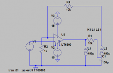
Here is my schematic which AFAIK shows how it actually works. You can expand the mechanical side to include Bl modulation, suspension nonlinearity, etc.
But does the scheme really lower the distortion?
That, my friend, is the million dollar question.
My analysis, observation, and discussion is to present information that can be had with respect to the magnetic non linearity of the speaker. This based on my previous design and research in the high faultin fusion stuff..
If this information can be used in the audio realm, that is great. I hope it is useful..
Even if not, the discussion here is what it is all about...
jn
We could even take it one step further and apply an outer control loop on top of this...
I was thinking that the diff signal might actually be a useful entity for an outer loop of a current mode.
I've been recently designing in and taking advantage of an inner/outer loop structure in work, inner to quickly do large motions, and the outer to more slowly home in on final target. For example, a very quick move of 10 centimeters with a slightly slower settling to 20 nanometers..The tuning parameter are drastically different, but this satisfies the customer far better.
Stop me if I've said this before...I have presented my stuff here so that you really smart circuit and speaker guys can do that improvement....The amp-speaker interface has many more degrees of freedom than plain voltage drive which might be exploited to better a given driver significantly, at least that's what we all hope.
Or, to put it better...what part of collaboration is not understood?
jn
Last edited:
I've been recently designing in and taking advantage of an inner/outer loop structure in work, inner to quickly do large motions, and the outer to more slowly home in on final target. For example, a very quick move of 10 centimeters with a slightly slower settling to 20 nanometers..The tuning parameter are drastically different, but this satisfies the customer far better.
Sounds like the idea is to not use feedback for anything that can be predicted. Prediction is faster than the gradual approximation of feedback. And I think this is just another name for error correction.
It's interesting to note that in theory, with perfect prediction the only thing left for feedback to correct would be noise.
My Kuartlotron works so well because the behavior of transistors well within their ideal operating range is extremely predictable/repeatable.
That is quite accurate. Prediction is exact, feedback is reduction of error..
That said, the biggest problem I face at work is....wait for it..
prediction.
The motion vendor hinges their teachings on prediction.
The problem is, I have non linear problems to solve. Prediction on their part is entirely linear.
So there are about 20-30 young people who have learned that prediction is how you solve your motion problems..many of my slides are about how prediction is the problem. So many of the problems I have been tasked to solve are caused by the assumption of linearity.
So far, my ppt on problems that I have found, has 114 slides, with an average of 7 animations per.
Yes, teaching the youth how to solve 80% of the problems is great. More bang for the buck... Unfortunately, the real technical problems require a combination of EE, ME, controls theory, and process engineering. That last 20% is a b###h..
And I'm not getting any younger..
Prediction doesn't work very well for music. Sines, yah. Even two tone, not so bad..
But music, another story... State variables just don't cut it..
What we need is the smart guys who have been doing this for the last "fifty years" to step up to the plate...belly up to the bar so to speak, and discuss the stability/mag stuff, and engage the yoot of today in what is being discussed..
Yah, JC**...I'm talkin bout you...I look to you to help teach the yoot. (that, and I like pinging you).
jn
**ps. If I didn't appreciate your wisdom, I would not even mention your name..
Last edited:
I think that I will go along with whatever PMA finds.
Which is fine, for a simulation.
Unfortunately, simulation is only as good as the assumptions, and the package.
I've had problems in the past with the simulation packages. Especially with the initial conditions. They tend to be rather inaccurate for what I've done in the past..
Eventually, actual tests will be performed, data will be taken, and then discussion.
I hope you choose to engage...of course, that is your choice..you could simply promote bybees.. I prefer the former..
jn
Last edited:
I found this for plotting hysteresis of magnetic materials Magnetic Hysteresis :: Electronic Measurements I knew there was a simple real time way to do it having seen it in action back when I worked for a company making magnetic disks. It looks very similar to what we are exploring. I can possibly execute the analog version and plot it soon but not if someone points out problems. It will be interesting to see how the motion of the coil affects the hysteresis curve.
where might a linear variable differential transformer approach fit in to helping reduce distortion..... made on the voice-coil form.
THx-RNMarsh
Linear variable differential transformer - Wikipedia
THx-RNMarsh
Linear variable differential transformer - Wikipedia
Last edited:
I give a daffynition....
John thanks for responding. I’ll need some time for pinging back.
I didn't have a nonlinear model for the inductors. It could perhaps be made with the Chan model in LTspice. We would need an Le(I) plot and a hysteresis plot. If I had found one I might have already done it.
For that detailed model , look here
The LTspice Saturating Inductor Model - Introduction and Power Stage Design | Coursera
The part that all the seven parameters are plugged into LT Spice is at 10:25 (I’ve checked it, Spice doesn’t object to the syntax)
I found this for plotting hysteresis of magnetic materials Magnetic Hysteresis :: Electronic Measurements I knew there was a simple real time way to do it having seen it in action back when I worked for a company making magnetic disks. It looks very similar to what we are exploring. I can possibly execute the analog version and plot it soon but not if someone points out problems. It will be interesting to see how the motion of the coil affects the hysteresis curve.
Demian the circuit works with transformers.
I had built a crude version, still have it. B-H Curve Tracer
A very good idea to test it on a speaker

George
You may have figured out what jneutron is seeing in his head, I wasn't able to.
Here is my schematic which AFAIK shows how it actually works. You can expand the mechanical side to include Bl modulation, suspension nonlinearity, etc.
In looking at your sim results, it does exactly what I predicted.
The Re amplitude is totally flat in the region of interest.
The Re phase is quite flat in the region of interest.
Entirely consistent with a current drive in operation. The only significant difference is my fb reads the non linear compliances of the magnetics, where current drive does not consider how those non linearities will affect the distributed Re. Distributed Re being the sum of all the parts which dissipate energy without storing/returning it the the system. Both current drive and my system compensate the entities which store/return. An ideal speaker with no iron hysteresis losses, no vc or iron eddies, would perform exactly the same in both systems.
The Vout is rising with frequency to drive through the VC inductance so this circuit cannot be used to drive a speaker with a crossover inductor.
When a real circuit is tested, the Re should have reduced H2 and H3. The Vout should have more distortion.
And again, the only way to really view the ability of the system to lower distortion is by acoustic measurements.
jn
Last edited:
One very important thing I neglected to mention.
If you subtract the fb from the Vout, you get the exact voltage the magnetic system requires to do it's job without worrying about the dissipative loss. That allows one to view in real time the non linearities which are occurring vs position of the voice coil.
For example, with a two tone drive, you could see how the drive changes w/r to Le(x), showing higher hf amplitude as the coil is further in the structure where there is higher Le, lower amplitude when it is towards the front where Le is lower. Some DSP would allow immediate viewing of these kinds of effects.
With circuits, dropping in a scope probe to examine points is a great diagnostic tool, the DVC setup I propose provides some previously unused diagnostics.
If I were trying to design a better speaker, I would want that diagnostic information.
jn
edit: I earlier mentioned non linearities in my motion work. One significant one is the spring constant of the motor's magnetic field. In a three phase servo or a stepper, there is an associated spring constant one uses in building a model of the motor's frequency response. Rotational inertia and motor spring constant define a second order low pass filter. As long as the torque asked of the motor is constant, the magnetic spring constant is the same, and the frequency plot (amplitude and phase shift) is constant. However, if I push back against that motor, the magnetic spring force increases, and the plot of frequency and phase changes. If I tune the system while the motor is being loaded I can really increase the gain of the system to fight that. The problem is, when I relax the force, that tuning can be sufficient to cause the system to oscillate. that is because changing the filter parameters will compromise the unity gain frequency and phase margin. Because my motion requirements are orders of magnitude slower than a speaker, I can use adaptive tuning algorithms to change loop gain by position, thereby optimizing the tune for the varying magnetic loading. (I mentioned sixth order, two are in the motor, two are in the physical structure as load mass and drive train, and two are within the electronics in a two pole filter that is used to filter the output drive signal to combat resonances of the physical system. the feedback is on the far end of those entities.)
This type of effect also occurs with a speaker. As the current increases, the magnetic spring force on the mass of the cone varies, the filter parameters (of the speaker model) will change with current. So in theory, an adaptive tuning algorithm could be used to harden the motion during high acceleration (current), and relax the gain when the current is lower. And, it is only dependent on the absolute value of the current, not on any feedback information.
Last edited:
Interesting point. This would mean with pure current drive we would see distortion in JN-voltage, and when regulating on the JN-voltage we would see distortion in the current signal. So if your claim is correct, regulating on the JN-voltage should give lower overall distortion (unless the distortion is strongly masked by more significant distortion mechanisms or some form of cancelling skews the results).[...]
Entirely consistent with a current drive in operation. The only significant difference is my fb reads the non linear compliances of the magnetics, where current drive does not consider how those non linearities will affect the distributed Re. Distributed Re being the sum of all the parts which dissipate energy without storing/returning it the the system. Both current drive and my system compensate the entities which store/return. An ideal speaker with no iron hysteresis losses, no vc or iron eddies, would perform exactly the same in both systems.
...which is a challenge in its own right. We would need to measure really close to the cone/dustcap to have a nice and clean response but the mic must handle high sound pressure with neglegilble HD/IMD distortion.And again, the only way to really view the ability of the system to lower distortion is by acoustic measurements.
And hopefully the solution is affordable for diyaudio members. I don't think anyone here can spend anywhere near magnetic budget of a Fusion Reactor.... if your claim is correct, regulating on the JN-voltage should give lower overall distortion (unless the distortion is strongly masked by more significant distortion mechanisms or some form of cancelling skews the results)....
We would need to measure really close to the cone/dustcap to have a nice and clean response but the mic must handle high sound pressure with neglegilble HD/IMD distortion.
IME this is possible, you will find a compromise between SPL high enough but not overloading the mike and still having good S/N. There is a limitation for the nearfield measurement re upper frequency, it is usable to say 700Hz for a 5" speaker (I have not the formula in my head right now), for higher frequencies the phase differences (from different geometrical points of the cone) make the measurement of freq resp unreliable.
The measurement I made was within 25mm of the dustcap with a 1" B&K. It was well within the dynamic range at the 1V drive level. HF measurements made so close will have little bearing on what you will get at a listening position since everything from the cone angle to the glue on the dome affect the measurements 1M+ away.
I have an amp and a box now.
My experiments with LTspice have not suggested good results even with a "perfect" transformer. But I think I have a workable solution for DC stability. The inductance is the measured inductance at rest at 1 KHz (same for both coils). The inductance increases when the cone is pushed in to 550 uH or more and drops to around 380uH pushing out for both coils.
However very little time to futz between now and the 26th it seems.
Attachments
- Status
- Not open for further replies.
- Home
- Member Areas
- The Lounge
- John Curl's Blowtorch preamplifier part III