Better still, a middle ground that Rod Elliott advocates and adjust the amp's output impedance to suit the speaker?
But can you change the impedance fast enough per octave to make it worth it?
But can you change the impedance fast enough per octave to make it worth it?
You mean an on the fly spectral analysis/impedance shift on a music signal?
I don't think so..
jn
Yes, you are.
Give me 10 minutes.
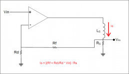
Ok...This circuit, L = 0. Vrs is Vin times (Rd+Rf)/Rd, or Vin times K, K = (Rd+Rf)/Rd.
Lets make Ls =1uH. What is the voltage at Rs? What is the phase at Rs?
2 uH..What is the voltage and phase at Rs?
The feedback is trying to keep the voltage at Rs equal to Vin times K and in phase, no matter what the inductance in series with it is (within the limit of the amp compliance voltage). AND, more importantly, no matter what that inductance is trying to do, pull or return energy to the system.
The problem historically, is how do we differentiate the actual real resistive part of the coil impedance from the terminal voltages?
We can try DSP, but we need to know the position, velocity, and acceleration of the coil in the gap.
Or, we can couple to all the inductance, and subtract it out. That is what I am doing with the co-wound pickup coil.
jn
The circuit in your post is a current drive. The same circuit as I use for the current drive of tested speakers.
Attachments
The circuit in your post is a current drive. The same circuit as I use for the current drive of tested speakers.
That specific diagram was to show something in particular. You understand current drive, this is almost current drive, but this is not quite the same. I drew it that way, eliminating the 1:1 transformer that is the DVC, and connecting the feedback directly at the model Rs rather than make another Rs, with dotted lines indicating it is the exact same voltage as the model Rs. But implicit in my drawing is the fact that the resistance is part of the voice coil and immersed in the magnetic circuit. An external viewing resistor is supposed to be rock solid.
1. I am viewing the exact coil real impedance component. You look at an external resistor.
2. I control the exact voltage the resistive portion of the coil has. You control the exact voltage on an external sense resistor.
3. I do not compensate for voice coil heating, just a pure voltage across the distributed resistance which allows compression. You can cause thermal runaway if not careful, but avoid compression.
4. I automatically compensate for hysteresis of the magnetic circuit**, you cannot do that with current control. And because that is position dependent and creates H2, I have a slightly better handle for cleaning some of that up. Especially when it causes intermodulation products.
I believe your technique is frequency limited and I believe requires tuning to accomodate the speaker. (I would be happy to learn otherwise from you).
I believe my technique is not, and does not require adaptation to the load. (but again, the jury is out on that, we are learning as I type.)
Both techniques are capable of reducing H2 and H3, and from your nice model, it appears both can extend the lower frequency region below normal resonance.
Which is best, who knows.
Which is simplest, who knows.
There may be a hybrid of both that is even better, who knows.
Hopefully we learn from others till we die..
I do, from many on this forum, and thank all for the discussions. I look forward to seeing how my technique helps or hurts, and I cannot think of any people who are more qualified to test my assumptions than peers here who may not agree with me..
jn
**Hysteresis can be reduced, but that will cost a lot in iron. As well, running gap fields in the 1 to 1.5 tesla range with iron means you are so close to saturation that just looking at it causes non linearity..we could do some vanadium alloys to really get up there, or even just a ring of it around the gap and the entire pole piece, but again that is very expensive.
pps..ok, now I'm done editing...
Last edited:
connecting the feedback directly at the model Rs rather than make another Rs, with dotted lines indicating it is the exact same voltage as the model Rs.
1. I am viewing the exact coil real impedance component. You look at an external resistor.
2. I control the exact voltage the resistive portion of the coil has. You control the exact voltage on an external sense resistor.
From the point of view of circuit theory, I see no difference if I take your Rs (voice coil resistance), put it up behind the voltage amp and replace the Rs of your schematics (which was connected to gnd) by a reference resistor Rref, value Rref = Rs. This Rref is now a current sensing resistor, same Io flows through the coil and the upper serial Rs makes no difference in the coil signal, it only rises voltage at amp output. The only difference would be that before the Rs might have been nonlinear, like temperature dependent.
Attachments
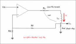
Your circuit theory view is entirely accurate, that is not the problem.From the point of view of circuit theory, I see no difference if I take your Rs (voice coil resistance), put it up behind the voltage amp and replace the Rs of your schematics (which was connected to gnd) by a reference resistor Rref, value Rref = Rs. This Rref is now a current sensing resistor, same Io flows through the coil and the upper serial Rs makes no difference in the coil signal, it only rises voltage at amp output. The only difference would be that before the Rs might have been nonlinear, like temperature dependent.
You make the incorrect assumption that all of the current that flows through Rs contributes to the BLI product and therefore voice coil force.
That is incorrect.
edit: I do my best to try and keep up with you guys with much of what you post, I try not to stare at the floor too much as I drool.
But E/M theory is not one of those subjects I have a problem with.
jn
Last edited:
How does the DVC circuit compensate for magnetic hysteresis in a way that normal current drive would not? In current drive you are increasing series impedance, in the DVC circuit you are decreasing EMF voltage. Both do the exact same thing just from a different approach.
You make the incorrect assumption that all of the current that flows through Rs contributes to the BLI product and therefore voice coil force.
That is incorrect.
edit: I do my best to try and keep up with you guys with much of what you post, I try not to stare at the floor too much as I drool.
But E/M theory is not one of those subjects I have a problem with.
jn
1) so a part of the current that flows through Rs is lost somewhere? This seems to violate Kirchhoff law.
2) I have no doubts about your knowledge of E/M theory.
1) so a part of the current that flows through Rs is lost somewhere? This seems to violate Kirchhoff law.
I think he means that the magnetic hysteresis shunts the generated EMF, thus a portion of the current does not generate force. IE a similar mechanism as an aluminum voicecoil former.
Some. A mere ring around the center pole doesn't seem to reduce current distortion notably, but a sleeve close to the voice coil has a considerable effect, perhaps worth 10 dB at best. As for eddy currents in the pole pieces or rings, I don't think they constitute any distortion mechanism (if you mean that) but rather tend to reshape existing (hysteresis) distortions.jneutron said:Have you tested any speakers with shorting rings? With a non conductive former, you should be able to see the modulation of the eddy drag as the vc is behind center position. That would require a current drive of course, as Le(x) would be a confounder.
Superficially. After some mental simulation I arrived quite at the same conclusions as some others here. It is in effect current drive for the EMF portion of the load impedance and voltage drive for the wire resistance portion.jneutron said:Have you been following the discussion of my pickup coil feedback design?
Any energy that shunts around the force generating mechanism is not seen by current drive. It may increase the voltage requirements through compliance but cannot control for loss of transfer function ( transfer function being the conversion from current to force.How does the DVC circuit compensate for magnetic hysteresis in a way that normal current drive would not? In current drive you are increasing series impedance, in the DVC circuit you are decreasing EMF voltage. Both do the exact same thing just from a different approach.
Any losses which cannot be seen by the current means the coil is not in the exact position you want it to be. Under current drive, you do not care where the voice coil is, nor do you care what it's velocity is nor it's acceleration. You only care about current.
In my scheme, any change in the coil velocity is seen by the pickup coil, and the difference is seen at the feedback terminal.
1. I refuse to break the law..1) so a part of the current that flows through Rs is lost somewhere? This seems to violate Kirchhoff law.
2) I have no doubts about your knowledge of E/M theory.

2. I have doubts about my knowledge of E/M theory..
. Luckily, I have people here who are far above me in that regard...I am unaware of any. If I were, I'd be waiting for that call from Stockholm.Is there any magnetic situation/environment where Kirchhoffs law is not valid for an electric circuit?
//
Yes, you mention two of the mechanisms.I think he means that the magnetic hysteresis shunts the generated EMF, thus a portion of the current does not generate force. IE a similar mechanism as an aluminum voicecoil former.
Reduction of BL modulation in the magnetic circuit is expected to be beSome. A mere ring around the center pole doesn't seem to reduce current distortion notably, but a sleeve close to the voice coil has a considerable effect, perhaps worth 10 dB at best. As for eddy currents in the pole pieces or rings, I don't think they constitute any distortion mechanism (if you mean that) but rather tend to reshape existing (hysteresis) distortions.
really small. At the gap where the flux rate of change is greatest, you can't put a ring anyway.
Eddy currents at the pole pieces and front plate are a consequence of moving current past them as well as time varying currents. It gets worse when you consider a two tone stimulus where a fast time varying current is being dragged past a conductive surface by a larger slower current. The front plate would be better as a laminated structure, pole as ferrite or EDM cut to keep thicknesses below .5mm.
That is a perfect analysis.After some mental simulation I arrived quite at the same conclusions as some others here. It is in effect current drive for the EMF portion of the load impedance and voltage drive for the wire resistance portion.
Jn
Last edited:
So, the voltage seen at the feedback terminal is not Vrs per se.... any change in the coil velocity is seen by the pickup coil, and the difference is seen at the feedback terminal....
So, the voltage seen at the feedback terminal is not Vrs per se.
It is quite close. It just cancels out all reactance that both coils see together.
ETM summarized the design quite well.
Jn
1. I am viewing the exact coil real impedance component. You look at an external resistor.
If Irs=Ire, then surely Vrs will contain exactly the same distortions Vre does.
What is the benefit you derive from having the exact Vre? I see you also have the exact EMF voltage as well across the second coil, but your idea seems to be about reducing distortion, not taking measurements?
Also, you are not viewing all of the real impedance component. The EMF provides some of the real component as it is a transformer coupled to a lossy magnetic system. When you remove the EMF you remove that as well.
Unless there is some sort of proximity/skin effect going on in the voicecoil causing distortion which can be compensated out.
Last edited:
...ETM summarized the design quite well...
His statement brings more questions, what difference should be noted between a current and a voltage drive for a resistance? What do we miss? Is there some recent finding the rest of us are unaware of? Clearly some important points are not getting through..... It is in effect current drive for the EMF portion of the load impedance and voltage drive for the wire resistance portion.
However, I hope measurements and plots could clarify what you mean later on.
How best to simply explain without losing content.If Irs=Ire, then surely Vrs will contain exactly the same distortions Vre does.
What is the benefit you derive from having the exact Vre? I see you also have the exact EMF voltage as well across the second coil, but your idea seems to be about reducing distortion, not taking measurements?
Also, you are not viewing all of the real impedance component. The EMF provides some of the real component as it is a transformer coupled to a lossy magnetic system. When you remove the back-EMF you remove that as well.
Unless there is some sort of proximity/skin effect going on in the voicecoil causing distortion which can be compensated out.
First, losses are not reactive, they are resistive and in phase with the voltage.
The load is a series connection between a reactive element which has non linearities which are current, position, velocity, and acceleration dependent, and a resistive component which is also velocity, current, position and magnetically dependent(excluding temp).
Using a pickup coil, the reactive portion of that load can be subtracted out.
Leaving resistive and ignoring any non linearity which is coupled by flux.
How do you compensate out proximity/skin effect?
Jn
It's a wonderful discussion, no? Every single one of us is skirting the edge of our knowledge and understandings. That is the best.His statement brings more questions, what difference should be noted between a current and a voltage drive for a resistance? What do we miss? Is there some recent finding the rest of us are unaware of? Clearly some important points are not getting through.
However, I hope measurements and plots could clarify what you mean later on.
Yes, I look forward to measurements and plots, confirmations and refutations.
I hope ETM also gets into measurements.
I am working on the capability of co-winding a sense coil, should someone with test capability be interested in a DVC conversion of a driver using a recone kit.
Jn
How best to simply explain without losing content.
First, losses are not reactive, they are resistive and in phase with the voltage.
The load is a series connection between a reactive element which has non linearities which are current, position, velocity, and acceleration dependent, and a resistive component which is also velocity, current, position and magnetically dependent(excluding temp).
Using a pickup coil, the reactive portion of that load can be subtracted out.
Leaving resistive and ignoring any non linearity which is coupled by flux.
Jn
The proximity effect was me twisting my brain into a pretzel to find a distortion which is not subtracted by the second coil.
The in-phase losses come from the EMF part of the equivalent circuit, not Re. As such they will be subtracted by the second coil, leaving only Icoil*Re=Vre.
If the EMF drops due to eddy current shunting, the EMF from the second coil will drop identically, subtracting that distortion as well as anything else coming through EMF.
- Status
- Not open for further replies.
- Home
- Member Areas
- The Lounge
- John Curl's Blowtorch preamplifier part III