
SONY SA-H7900 Service Manual download, schematics, eeprom, repair info for electronics experts
Works quite well, nice sense of clean 'solid' power in the lows for a pretty small pretty low powered box.
Some degree of MFB is pleasantly useful, it may be a mistake to go all out for total error correction.
Dan.
Last edited:
Another forum member posted some dual voice simulations back in 2010.
Dual Voice Coil Speed Feedback
Also thanks.
That effort also does not find the magnetic problems.
jn
Another forum member posted some dual voice simulations back in 2010.
Dual Voice Coil Speed Feedback
Also these two from the same member:
AVFB loudspeaker
Philips Motional Feedback (MFB)
And three Ltspice loudspeaker modeling related threads from stepf:
Thiele-Small reloaded with LTspiceIV
Monacor SP-100-8 LTspiceIV simulations
Monacor SPH-225C - advanced current drive
George
You are always welcome, of course.Thanks.
Note that one side of the pickup coil goes to ground. So they also do not cancel out any magnetic non-linearities.
jn
What is the nature of such magnetic non-linearities, and what do you expect are the subjective and objective effects of such magnetic non-linearities in such a MFB system as this Sony example, and ilk.
Dan.
You are always welcome, of course.
What is the nature of such magnetic non-linearities, and what do you expect are the subjective and objective effects of such magnetic non-linearities in such a MFB system as this Sony example, and ilk.
Dan.
Voice coil inductance change vs excursion.
Eddy dragging loss.
Proximity effect voice coil resistive increase.
Iron hysteresis.
That simulation for example, they show the coil L and the coil R in series for the model.
The problem (prior to my design) is that the R is a distributed R, through the entire coil L. By using the second coil as I have shown, the R can be seen by itself, as I subtract out the distributed L.
Look at Demian's plots, specifically the fourth one. The subtractive voltage (difference) he posts as green, is the exact resistive voltage remaining after removal of the magnetic stuff. Note the 2nd and 3rd harmonic spikes. They are there because the magnetic non linearities are in series with that R, so affect the voltage. (no idea what the 10th harmonic actually is..is he measuring on an airplane??)
By using that R voltage in the feedback loop, the amplifier will now ignore the inductive part of the load, trying to only put the voltage across that R.edit: that is why I said this design will compensate out a series crossover inductor..
This technique gets around (compensates) every non linear effect that affects the flux in the system and is in series with the coil R.
I am confident that this will reduce the 2nd and 3rd harmonic in the acoustic signal as measured by Demian.
jn
ps...the beautiful aspect of this technique is that it is not filtered, no DSP, so that it is not frequency dependent. It will work on any speaker at any frequency of operation.
pps. Another beauty is that you do not need to co-wind the sense coil on both layers of a two layer coil. I can add the sense coil to a recone kit using adhesive coated magnet wire, cure it, and while it has half the turns of the primary, all I have to do is double the feedback resistance to compensate.
Last edited:
JN, a little favour please as it seems that you are adept in magnetic sims.
If I were to twist two enameled wires, say 0.3mm, (enamel thickness I am not certain but I glean around 0.025mm or so) so as to form one 'effective conductor', and then twist this effective conductor with a duplicate so as to form a (four wire twin parallelled) twisted pair, what would be the characteristic impedance of this twisted pair ?.
What spacing of the 'effective conductors' is required to obtain 90R characteristic impedance ?.
Thanks in advance.
Dan.
Bring it on.......This technique gets around (compensates) every non linear effect that affects the flux in the system and is in series with the coil R.
I am confident that this will reduce the 2nd and 3rd harmonic in the acoustic signal as measured by Demian.
jn
ps...the beautiful aspect of this technique is that it is not filtered, no DSP, so that it is not frequency dependent. It will work on any speaker at any frequency of operation.
pps. Another beauty is that you do not need to co-wind the sense coil on both layers of a two layer coil. I can add the sense coil to a recone kit using adhesive coated magnet wire, cure it, and while it has half the turns of the primary, all I have to do is double the feedback resistance to compensate.
 .
.Edit: Thanks for the summary, let's see if your 'confidence' is fulfilled.
Dan.
Last edited:
Twisting two magnet wires probably gets you into that range already. If you look at Cat5e cable, the Z is a direct function of the geometry and insulation. If you scale the pair, as in double the wire diameter and insulation thickness, you will get the same approximate impedance. Only by thinning the insulation does the characteristic Z go down.JN, a little favour please as it seems that you are adept in magnetic sims.
If I were to twist two enameled wires, say 0.3mm, (enamel thickness I am not certain but I glean around 0.025mm or so) so as to form one 'effective conductor', and then twist this effective conductor with a duplicate so as to form a (four wire twin parallelled) twisted pair, what would be the characteristic impedance of this twisted pair ?.
What spacing of the 'effective conductors' is required to obtain 90R characteristic impedance ?.
Thanks in advance.
Dan.
Magnet wire is thinner insulation relatively, so twisting a pair should go below 100.
Doing what you say may be counter to lowering the impedance, as the capacitance is going to be wonky due to uneven spacing. I am guessing it would go higher than 100.
If you make it and have access to a LC meter, measure both.
Z =sqr(L/C)
jn
Demian is doing great stuff, I thank him for taking the time and expense..Bring it on
Edit: Thanks for the summary, let's see if your 'confidence' is fulfilled.
Dan.
I also look forward to KSTR's tests and comments, he has a very good understanding of my theory..
jn
If you make it and have access to a LC meter, measure both.
Z =sqr(L/C)
You can also tweek the twists per foot, IIRC CAT5 uses that to do something about crosstalk(?) not sure it changes the Z much.
I use a power drill on a loop around a nail or chair leg, it gives a fairly uniform twist if you keep uniform tension while twisting (slow speed helps).
Last edited:
JN, a pea sized piece of my 'goop' (as somebody here named it, lol) when placed at the centre of the magnetic assy back plate (which is also the extension through the centre of the VC) and/or somewhere on the ferrite magnet ring itself and/or somewhere on the iron front plate quite markedly changes the character of sound of typical ferrite/iron drivers.Voice coil inductance change vs excursion.
Eddy dragging loss.
Proximity effect voice coil resistive increase.
Iron hysteresis.
The subjective effect is lower lows, more clear and more dynamic lows, greater sense of power and perfect separation of sources of lows..... altogether much more fun when compared to the untreated version.
The point is that typical ferrite magnets are noisy (and I'm also sayin that the character of this magnetic noisiness can be changed at will) and this might reflect in your feedback signal.
Just some food for thought.
Dan.
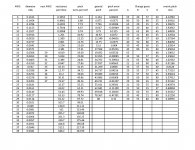
In working the problem of winding, I am thinking about using my mini lathe to make a coil for tests. It has a set of change gears for cutting threads, and there is an online calculator for determining the size of the four gears needed, and their location on the mechanics (positions A, B, C, and D.)
Here is a table with: AWG, wire diameter, pitch, change gear tooth counts, and winding error percent.
In the third column is the tap wire size that will nest in a coil made with the first column gauge.
Course, if one only needs to wind a half the turns coil on the top of a two layer coil, the first and third columns are the only thing of value.
jn
Attachments
Last edited:
JN, a pea sized piece of my 'goop' (as somebody here named it, lol) when placed at the centre of the magnetic assy back plate (which is also the extension through the centre of the VC) and/or somewhere on the ferrite magnet ring itself and/or somewhere on the iron front plate quite markedly changes the character of sound of typical ferrite/iron drivers.
The subjective effect is lower lows, more clear and more dynamic lows, greater sense of power and perfect separation of sources of lows..... altogether much more fun when compared to the untreated version.
The point is that typical ferrite magnets are noisy (and I'm also sayin that the character of this magnetic noisiness can be changed at will) and this might reflect in your feedback signal.
Just some food for thought.
Dan.
While I do not believe in your "goop", if it does impact the magnet linearity, it should show up in the difference coil test.
With Demians setup, it would be in the spectra. However, given how noisy his spectral plots are, I cannot see how a subtle effect would be seen in the noise.
With the second coil being used as the feedback node in my "incredibly complex" circuit diagram, the voltage being presented to the drive coil will be distorted by the magnetic non linearities, just enough to clean up the resistive voltage, so there would be the second place to look.
For subtle stuff such as what you claim, the speaker would certainly have to be either in a vacuum, or an anechoic chamber..
I personally would not hold my breath, but one never knows..
jn
I didn't spec turns per inch/foot my bad, cat5/cat6 turns ratio would be a benchmark.You can also tweek the twists per foot, IIRC CAT5 uses that to do something about crosstalk(?).
I'm wanting a non directional twisted pair.....USB 90R.
Yo, a hook made of coat hanger wire in a battery drill, same attached to a table leg, pre coat the wires with a touch of some kind if lubricant, organic coconut oil works well for me.I use a power drill on a loop around a nail or chair leg, it gives a fairly uniform twist if you keep uniform tension while twisting (slow speed helps).
Twisting forth then back then forth with lubricant makes for a more 'relaxed' twisted pair.
Dan.
Last edited:
JN, I was with you until your last two sentences.......please understand that I don't bother, ie I plain don't make any of my statements until well proven, admittedly anecdotally/subjectively BUT relating matching subjective opinions of at least several subjects.While I do not believe in your "goop", if it does impact the magnet linearity, it should show up in the difference coil test.
With Demians setup, it would be in the spectra. However, given how noisy his spectral plots are, I cannot see how a subtle effect would be seen in the noise.
With the second coil being used as the feedback node in my "incredibly complex" circuit diagram, the voltage being presented to the drive coil will be distorted by the magnetic non linearities, just enough to clean up the resistive voltage, so there would be the second place to look.
For subtle stuff such as what you claim, the speaker would certainly have to be either in a vacuum, or an anechoic chamber..
I personally would not hold my breath, but one never knows..
jn
Many drivers have a reflective decorative aluminium sticker on the back of the magnet assy.....ever tried removing it and taking another listen ?...the result may surprise/intrigue you.
Dan.
Last edited:
Demian --- are the two coils on your test speaker wound on top of each other or side by side?
Max --- you can apply liquid 'rubber' or other damping compound (goop) to the magnet assembly and speaker frame, also.
Enjoy, clearer, cleaner sound. Better speakers will have thick/heavy cast metal magnet/frame assembly and benefit less from damping goop applied.
THx-Richard
Max --- you can apply liquid 'rubber' or other damping compound (goop) to the magnet assembly and speaker frame, also.
Enjoy, clearer, cleaner sound. Better speakers will have thick/heavy cast metal magnet/frame assembly and benefit less from damping goop applied.
THx-Richard
Last edited:
JN, I was with you until your last two sentences.......please understand that I don't bother, ie I plain don't make any of my statements until well proven, admittedly anecdotally/subjectively BUT relating matching subjective opinions of at least several subjects.
Many drivers have a reflective decorative aluminium sticker on the back of the magnet assy.....ever tried removing it and taking another listen ?...the result may surprise/intrigue you.
Dan.
My point was any measurement would need a large reduction in background noise. Since no measurement of this has ever been shown, the only thing left would be that it's too low. Hence my statement about removal of background.
jn
Second difference between coils,
The difference between coils, 2nd image yellow track, almost exactly reflects inverted impedance curve of the speaker used.
- Status
- Not open for further replies.
- Home
- Member Areas
- The Lounge
- John Curl's Blowtorch preamplifier part III