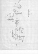
Dreamth put up a few interesting schematics. The first schematic (on the left) is typical of how we designed tape recorder reproduce stages back in the 1960's. These were relatively crude designs but they had some advantages over IC's. First each is truly class A, second the open loop bandwidth is necessarily high because the total feedback available is so low. Subjectively, these circuits beat most IC's even today's. Shocking isn't it?
The fourth circuit shown has qualities that I value and have used in master tape recorder reproduce circuits, BUT instead of an IC for the following stages, I inserted the 77 line amp (in the triangle) instead. Even today this circuit holds up in one of the World's finest analog tape recorders, Dave Wilson's Ultramaster. This is what it takes to get world recognition for your design, not just IC's.
The fourth circuit shown has qualities that I value and have used in master tape recorder reproduce circuits, BUT instead of an IC for the following stages, I inserted the 77 line amp (in the triangle) instead. Even today this circuit holds up in one of the World's finest analog tape recorders, Dave Wilson's Ultramaster. This is what it takes to get world recognition for your design, not just IC's.
For some unknown reason i feel the need to torture you with some more photos")
Lots of nice electrolytic cap coupled circuits... many of those 2-transistor feedback to emitter types everyone loved so much.
Got any without the I/O electro coupling caps on every stage?
Reconfigure them into my 4 transistor compl push-pull (CMA) and get rid of all those electro coupling caps throughout the product.
THx-RNMarsh
Last edited:
Installing a simple RC filter on the input of a 7815 can really help it out. Lower the high frequency garbage before it gets into the reg.
and you could also use a pre-reg -- say a 24vdc IC reg feeding the 15 volt IC reg. get some really good line isolation/reg.
and, as I did with my preamp power in 1980.... load the IC reg.... as the output of the ic reg is an emitter follower, increasing the load current on it, can improve its performance; Lightly loaded ic reg dont reg as well as they do more heavily loaded. Just an R from output to ground that equals the circuit load. Try it.
-RNM
Last edited:
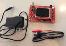
An oscilloscope I bought for $18 on eBay
The (in)famous DSO-138 single channel oscilloscope.
Notice the 1X "probe" and the plastic suction cup feed that adhere the PCB to the tabletop.
It works okay; bandwidth is about 0.2 MHz, triggering is fairly wonky on anything other than a simple waveform like a sine wave or square wave.
_
The (in)famous DSO-138 single channel oscilloscope.
Notice the 1X "probe" and the plastic suction cup feed that adhere the PCB to the tabletop.
It works okay; bandwidth is about 0.2 MHz, triggering is fairly wonky on anything other than a simple waveform like a sine wave or square wave.
_
Attachments
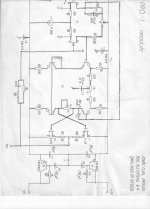
The first schematic is Nakamichi CR4.I had two of them .Their sound was perfect for me.Sold them for the money as i was in real trouble at some point.I still buy and sell vintage audio equipment from time to time just to have a living.I open and look into each schematic every time i can.
Now for Richard:
I consider a BIG minus a circuit without capacitors in the signal path and i did a few thousands tests especially on this matter with diverse circuits. Capacitors are blamed for all sorts of losses, but at least starting with the Nichicon Muse line all the problems disappeared.There was actually a recent test done on AP for Nichicon muse and under 400mv dc over the cap's pins there's no detectable distortion over -120db.
A second problem solved by capacitors is that their charging is exponential and if their values are right they get into a covariance function with the transistors's exponential law and if you look at this pictures you might get the idea: Covariance functions
It's just an idea...i'm not a mathematician!!!don't judge me if i got it all wrong just out of enthusiasm!
It might also be the secret behind QSC amplifiers that nobody really understood other than through the practical value of it..Patrick Quilter had this crazy idea to use the filtering capacitor as coupling capacitors through the speaker in the collectors of the final stage for many practical reasons, but i wondered for some time : WHAT IF ?!.... cause i fixed and listened to some of his amps and their sound is really good even though few people would consider its designs as high end, being in fact the cheapest touring equipment for decades.
I still dream to build a 100watts amp based on his designs with the most modern components cause i felt a lot of potential in its simplicity.
But now i'm going to tell that although Nakamichi zxl 1000 , the fourth picture in my other post that JC admired has the most accurate sound of all the Nakamichi line, nobody really likes it...while the most revered Nakamichi players were and still are all the others...those with lots of capacitor coupling stages.
Last edited:
The first schematic is Nakamichi CR4.I had two of them .Their sound was perfect for me..
Now for Richard:
I consider a BIG minus a circuit without capacitors in the signal path . starting with the Nichicon Muse line all the problems disappeared.. and their sound is really good even though few people would consider its designs as high end,
But now i'm going to tell that although Nakamichi zxl 1000 , the fourth picture in my other post that JC admired has the most accurate sound of all the Nakamichi line, nobody really likes it...
Well, if you LIKE it, then it's fine with me. But, I am not going to recommend Nichicon Muse be added to all modern direct-coupled designs any time soon.
Nor as a DIY mod of everything; adding C and $$ to all stages I/O's. Not even if they were Polyprop caps being added on.
But, that's just crazy old me. Too old to be taught new tricks, I suppose.
THx-RNMarsh
Last edited:
I consider a BIG minus a circuit without capacitors in the signal path
A second problem solved by capacitors is that their charging is exponential and
if their values are right they get into a covariance function with the transistors's
exponential law.
Shirley you can't be serious.
YouTube
Has it ever been published what Keith Johnson used in his tape machine for RR in the analog years?
I don't believe so. Its an interesting circuit and the record side uses the special focused cap head. I believe the vendor doesn't exist any more and making them is no longer possible. They were made from special amorphous iron alloy laminates and had a special bit of magnetic material in the record gap to narrow the gap width. It needs to work with a 4 MHz bias (and 500 KHz for the erase head). I worked with him on a variation 30(!) years ago that only produced one set of film recorders. I created a bias/erase circuit for it using a crystal oscillator and resonant tanks to get the necessary drive. He has some really original ideas for the record and playback circuits. As I remember they were all bipolar discrete. The RR machine is all point to point circuitry. They are different from the Spectral circuits he works with today.
I had this idea for a long time and actually it was shown to be true that properly made electrolytic capacitors have (and theoretically should indeed have) lower distortions than non-polarized film ones because the dielectric is much thinner in electrolytics, nor they show any piezzo effect being damped by a liquid.
I just studied chemistry and physics , i'm not an electronics engineer. I'm not absurd.I don't use them throughout, I'm not your usual swapping capacitor man, but when i can solve a very difficult problem with a small capacitor i will do it .
It's just that i lost interest in preserving theoretical bandwidth and phase up to gigahertz range when i can hardly hear 13.8khz on a simple test on youtube.By the way, it is already proven that hearing high frequencies or even perceiving them through the skull can enhance our mental abilities and increase our perception so a little bit of oscillation or high frequency, or white noise usually help...
I do understand the limits of integrated circuits, but if i'm going to use a circuit like the Nakamichi i'd only change the tl072 with opa2132 and the coupling capacitor with a Muse one and i'm sure that there's no other circuit on Earh sounding better as a tape head preamp and we are a few thousand guys thinking the same on this subject already on all sort of forums.
The CR4 is just a beast, that is true, i'd throw away any cd player for that cassette player at anytime.Now i have a Pioneer which has also lots of coupling capacitors, but i wouldn't trade it , nor i'd throw away my Dual 701 turntable for for any digital technology.
The beauty of analog sound with all its distortions or noise is simply irreplaceable, but for a while now i enjoy the fact that everybody give away their cd's and cd players for pennies. I'm living with other's garbage for a long time.
Didn't you have problems with rec head overheat?It needs to work with a 4 MHz bias (and 500 KHz for the erase head). .
At that frequency, the iron powder in the tape itself starts to melt.
No...i can't !Shirley you can't be serious.
YouTube
Anyway, no wonder you have so much trouble trying to pin people down on what evidence they will accept. People intuitively know they may need some wiggle room later if a study turns out in way they don't feel comfortable with.
Works for both sides of any question. I could easily say why do some people fight the idea of un-sighted listening with such a passion?
We have a paradoxical behaviour about diy...
We expect that tweaking and replacing components by experiment would give us more control than a designed circuit
I have never believed that. I have never considered part swapping to be coextensive with DIY. Part swapping, opamp or capacitor rolling etc, have never interested me in the least. Want to know how some new opamp sounds? Fine, but just shoving it into a circuit designed for a different opamp is no way to find out.
I could easily say why do some people fight the idea of un-sighted listening with such a passion?
To consider this question first it would need instantiation. Who are these people, do any of them frequent this thread?
To consider this question first it would need instantiation. Who are these people, do any of them frequent this thread?
Yes, JC himself has said for him all differences disappear with blind listening numerous times. So do you agree or disagree that un-sighted is a necessary condition? When you read the numerous op-amp and capacitor rolling threads do you accept all the comments without regard to the conditions? Some here call this all valid data and throw it all together and just count the votes with no weighting.
Last edited:
Yes, JC himself has said for him all differences disappear with blind listening numerous times.
Yes, I've noticed him saying this too. So @JC - does it seem to you that you 'fight the idea of un-sighted listening with a passion' ? Or do you simply avoid it - in the way I avoid Brussels Sprouts - because it doesn't suit your purpose?
- Status
- Not open for further replies.
- Home
- Member Areas
- The Lounge
- John Curl's Blowtorch preamplifier part III