Sorry, Joe, but I see no "Back EMF" here. In the low frequencies, the resonance peak of the bass speaker, in the upper range, the typical increase due to the the voice coil inductance. With the typical effects of Eddie currents on the linearity.
Sorry, Joe, but I see no "Back EMF" here.
My take is Joe calls any temporary energy storage in a reactive component "back-emf" when it is given back to the system. With deference to George's comment I could get past these eccentricities if there was a consistent story that did not violate first principles.
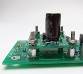
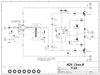
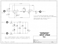
Here's the amplifier (designed by Nelson Pass: look Ma, no feedback!) and also the Scott-Wurcer-IC-input-stage (designed by me: muchas feedback). It is the latter schematic which is implemented on a daughterboard that uses M3 bolts to make electrical connection to the motherboard. The bolts are actual "components" on the motherboard schematic, complete with "symbols" and everything. Shazam!You should see his first attempt at the all-SMD board that includes a Scott Wurcer-designed SOIC_8 chip: Oy vey!
_
Attachments
My take is Joe calls any temporary energy storage in a reactive component "back-emf" when it is given back to the system. With deference to George's comment I could get past these eccentricities if there was a consistent story that did not violate first principles.
He is also not entirely wrong. The voltage developed across an inductor when the current through it changes is sometimes referred to as "back EMF", though usually as "induced EMF". However he wants to lump everything except voice coil resistance together and call it "back EMF", which just confuses people and obscures his meaning. "Reactance" isn't that difficult a concept and is mathematically well defined.
This seems relevant:http://www.daytonaudio.com/media/resources/290-226-dayton-audio-nd91-8-klippel-test-results.pdf
Still not sure about the Bl(i) linearity of an air coil motor though... I thought Jneutron said something about that in the past?
Those were great links, thank you.
It is good to see klipple agreed with me on the inductance changes as the coil extended forward vs reverse. I think that is excellent work (despite the fact that it is in total agreement with me (as non biased as that could be
 )).
)).I would like to see that chart extended to detail how eddy losses come in as real components disguised as vc pure resistance, and they should look at flux dragging as well.
What do you mean about the Bl(i) non linearity of an air coil motor? Are you thinking about the issue of magnetic permeability vs flux?
Is klipple a person? I would love to discuss this stuff with him/her/them if it were possible.
Richard,
Your earlier amp mod...I note that performance above 60 he was definitely worse with your mods, from your graphs.
Why?
Jn
I believe his name is Wolfgang Klippel, there is a ton of driver design infographics with his name. Holds seminars and all sorts of stuff.
This is a good one too:
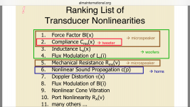
http://www.almainternational.org/ya...ses_in_microspeakers_alma_2013-1.10691701.pdf
I'm trying to figure out why KSTR says Bl(i) isn't helped by current drive.
This is a good one too:
http://www.almainternational.org/ya...ses_in_microspeakers_alma_2013-1.10691701.pdf
I'm trying to figure out why KSTR says Bl(i) isn't helped by current drive.
Richard,
Your earlier amp mod...I note that performance above 60 he was definitely worse with your mods, from your graphs.
I noticed that too. Richard said the test was done without changing the amp input levels.
The .15R resistor introduces a 2.8R series resistance to the output of the amplifier. So I don't know what the woofer resistance was but if it's around the same value some of the reduction could just be due to a reduction in power going to the speaker.
Lots of uncontrolled variables to sift through without having any empirical knowledge.
The Q is lower and broader at resonance as well. It is higher at 30Hz also. The two peaks are spread out. The -3dB was extended slightly lower freq.
Where the Z resonance peak would be in the driver, the thd is lowest by 1/2.
A different Re might shift this up or down. or spread out further or more narrow.
The JBL D130 15 " diam driver has a 3 inch voice coil diam. I would guess the DC R is close to 3 Ohms.
THx-RNMarsh
Where the Z resonance peak would be in the driver, the thd is lowest by 1/2.
A different Re might shift this up or down. or spread out further or more narrow.
The JBL D130 15 " diam driver has a 3 inch voice coil diam. I would guess the DC R is close to 3 Ohms.
THx-RNMarsh
Last edited:
Yes, Bl is nonlinear with displacement as well, so this cannot be cured with the current drive.
I did some real life measurements on current drive few years ago, it helped only for a woofer in a closed box and only near resonance.
Current drive of speakers and speaker distortion
I did some real life measurements on current drive few years ago, it helped only for a woofer in a closed box and only near resonance.
Current drive of speakers and speaker distortion
I can understand how Bl(anything) isn't completely cured by current drive, but I'm trying to figure out if i changes Bl in a way that wouldn't also apply to an air coil motor. Or maybe it does apply to an air coil motor. In which case we appear to be screwed.
Even if Bl changes linearly with i, it is still distorting because of the i*i term Klippel mentions. So there is no need for modulated permeability to show that this is nonlinear. I don't see how this would not apply if the magnet were an air coil.
If I am correct, the only solution is to short out the flux modulation through the magnet with a shorting ring. Or... Perhaps a hall sensor. But that scares me.
Last edited:
- Status
- Not open for further replies.
- Home
- Member Areas
- The Lounge
- John Curl's Blowtorch preamplifier part III