It looks like Fischer Core series to me.
I think it's a Fischer low voltage series 105. But I can't find a part number for the male plug on their website or anyone who even carries these connectors. I'm assuming it's Fischer proprietary?
I just love those added ceramic caps and ferrite inductors, don't you? '-)
I think the best solution WRT making Blowtorch more bullet proof RF wise is
to use quality XLR's on IP and OP. Pin 1 directly to chassis, shell tab directly
to pin 1.
It is a fully balanced topology and should use XLR's anyway.
For those may have an RF interference problem, use HQ shielded balanced interconnects.
Very small film caps or NPO ceramics to chassis right at IP can also help.
However if you are using proper shielded / balanced interconnects with shield
connected to chassis at both ends there should be generally no problem.
T
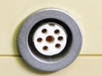
Could someone help me identify this connector? I need the male plug. Thanks for the help.
This looks like a Tuchel connector but I'm not 100% because center pin looks
larger dia and I don't see a thread - your pic is small.
http://www.preservationsound.com/wp-content/uploads/2012/05/Nagra_Tuchel.jpg
T
This looks like a Tuchel connector but I'm not 100% because center pin looks
larger dia and I don't see a thread - your pic is small.
http://www.preservationsound.com/wp-content/uploads/2012/05/Nagra_Tuchel.jpg
T
Center pin is larger and three pins on the left are spaced further apart.
I think it's a Fischer low voltage series 105. But I can't find a part number for the male plug on their website or anyone who even carries these connectors. I'm assuming it's Fischer proprietary?
Download the full catalog.
https://www.fischerconnectors.com/global/en/technical-specifications-full-version
Find your part number.
Try this outlet:
FISCHER CONNECTORS - Manufacturers
I won't use those IEC inlet filters and other things.
Commercial pre-built filters assume there is no capacitance on the AC lines and stupid stuff like that. They don't cut the subjective test, at all. The AC system is kind of a diverse ecosystem. This is why I made something to try and help tame it, that goes in the breaker box and acts to ease the recovery from complex impedance terror that is constantly going on.
Chokes should be oversized in amperes by a decent amount, is a simple rule to start with for AC.
I recommend trying a balanced power system as originally patented by Martin Glassband of Equitech. This will align all the reactive components in power filters in a symmetrical / balanced nature to ground.
I also recommend getting one with proper RCD protection as many after market balanced power solutions will negate the RCD protection in your fuse box.
However they can change the sound of a system and subjectively it's not to everyone liking. As an example I built one recently for kicks with a huge amount of RF filtering as well as some RC snubbing, all fully symmetrical. I plugged my Vox AC30 into it not expecting any real difference but it had quite a pronounced effect on the sound. In the end I decided I preferred it without the balanced traffo / filtering.
It had the effect of leaching out the midrange and warmth of the amp. At first I was taken by the extra clarity but after extended playing it just had lost some of it's mojo.
Mojo is everything with guitar amps!
")
T
Oversize chokes or none is a nice idea but unfortunately not legal to sell in most places and getting tougher on the restrictions all the time. This requires a bit more work on the power supply.
I'd really appreciate more details on this ^.
For example the LOFI uses a 3A CMC, but the transformer won't even get pass 1A.
On a PSU we did it uses a 17A CMC because the 10A CMC saturated too easily, despite the device being limited to about 4.125A.
In many cases double is sufficient. This is a general rule because once you start calculating it all out, rarely would say a 24A CMC be sufficient for 20A at 60hz - and so on. The ratings manufacturers give often look a lot better at DC, that's for sure.
I recommend trying a balanced power system as originally patented by
Martin Glassband of Equitech. This will align all the reactive components in
power filters in a symmetrical / balanced nature to ground.
T
Funny you mention it. I actually made a device for correcting the problems the Equitech has. The difference seems slightly subtle on some equipment, and the difference between listening or not due to fatigue on other. It goes along with my break box devices.
I think the balanced transformer system works ok, and see why studios etc like it. But the big truth is that it isn't necessary with a good power conditioner.
BTW guitar amps love PFC.
I want to thank those who have given constructive inputs as to RFI proof my CTC Blowtorch. Fortunately, I have no RFI problems at my location in Berkeley, so I don't think that I need to do anything special for the rest of my life, as it would appear. I have learned a thing or two from your inputs however, thanks again.
Funny you mention it. I actually made a device for correcting the problems the Equitech has. The difference seems slightly subtle on some equipment, and the difference between listening or not due to fatigue on other. It goes along with my break box devices.
I think the balanced transformer system works ok, and see why studios etc like it. But the big truth is that it isn't necessary with a good power conditioner.
BTW guitar amps love PFC.
I have talked in person to Martin.... The transformer does not remove CMN as much as he thought. The transformer -- tested all by itself, can do some good numbers but the power lines and loads themselves are not going to be Z balanced to any significant degree... Lucky to do better than 20dB, typically. I said to him and audience also in a talk we each gave for seminar on power line noise a few years back. I had him send me one of the transformers (largest he had) and measured it. I always go to the test gear and measure -- theory or CAD of one piece in a system, isolated by itself, isnt very realistic in distributed ac power field app.
A good power conditioner is best in removing LF to RFI noise.
Again, too much testing on gear in isolation and get unrealistic numbers in the field. Just like we do in audio systems.
THx-RNMarsh
Last edited:
All the COTS line filters are measured using a 50 Ohm line impedance which pretty much never occurs in reality. The datasheet values for attenuation are therefore very useful for comparing the filter performance of different products in a standardised test scenario that bares little resemblance to reality. If you look VERY carefully, you will find mention in the application notes that performance in an actual installation MUST be measured before any compliance declarations are made.
But then real engineering requires a careful read and understanding of what information the datasheet is showing.
But then real engineering requires a careful read and understanding of what information the datasheet is showing.
Yeah, anytime you see Insertion Loss as the Y-axis label on the graph you can assume they are using 50 ohm Z if they don't specify.
I've seen and used a few different types, but they were all the medical grade parts without the Y caps due to leakage current requirements. I probably wouldn't bother using one on Class I audio equipment using a linear supply. Could be useful if you have to undergo EMC testing though.
I've seen and used a few different types, but they were all the medical grade parts without the Y caps due to leakage current requirements. I probably wouldn't bother using one on Class I audio equipment using a linear supply. Could be useful if you have to undergo EMC testing though.
I'd really appreciate more details on this ^.
For example the LOFI uses a 3A CMC, but the transformer won't even get pass 1A.
On a PSU we did it uses a 17A CMC because the 10A CMC saturated too easily, despite the device being limited to about 4.125A.
In many cases double is sufficient. This is a general rule because once you start calculating it all out, rarely would say a 24A CMC be sufficient for 20A at 60hz - and so on. The ratings manufacturers give often look a lot better at DC, that's for sure.
What I meant is that to pass emissions testing is that some type of filter is needed so going without is difficult. The higher current ones tend to filter less so it just takes a bit more work. Then they have to have all the proper approvals that vary from country to country. Schaffner tends to be the best for approval because they have very complete paper work. Otherwise every part needs a stack of paper work if you are rolling your own and then testing that is rather expensive and the destruction of your equipment. The Schaffner is just a know quantity and recommended by CSA though the tests are still time consuming.
CSA is used by Korea and a good start for China for safety. Emissions testing is a whole separate thing.
Good supply design can help in the emissions making filter selection better from an audio stand point. High speed diodes snubbers etc help on the conducted and radiated letter you use a better filter. You are correct some of those ratings are optimistic.
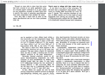
One might point out that in 1968 all the op-amps referred to here were discrete modules and nothing here came from the audio industry.
Yes. That’s why R. Stata makes the distinction between Op Amps and monolithic ICs.
The title of the article is almost misleading (provocative)
It’s mostly about properly reading the often incomplete specs.
It is also about improperly utilizing ICs which come with properly written specs
George
Attachments
MH, I'm afraid that listening impressions from you has no merit after that you have been proven, beyond reasonably doubt, to hear things that don't exists (re: the same checksum files). I felt I needed to post this so that an absence of comment was not to be regarded as a silent agreement.
//
//
I find ferrite split core filters sound good and bad. <snip>
Hi Richard,
I agree with you on that. How did you get around the channel swap that the A-77 does? I guess knowing about it is most of the problem solved.
Hi Miklos,
30 ips with tape has issues. The head bumps that were in the bass region now show up in a more audible range. Studer EQ'd them out, but that is expensive. I wouldn't recommend going to 30 ips for 2 dB of s/n improvement. At 15 ips you're already up in the 22 ~27 KHz range for top end response (on a Teac too). That's got to be enough top end for anyone.
A 15 ips half track sounds glorious. I just sold my BR-20 to a friend. Just wait until he hears what this can do!
-Chris
Hi Chris,
Yes, this subject come up a few years ago, possibly in the first thread, where JC also presented a schematic of his play back amplifier.
- Status
- Not open for further replies.
- Home
- Member Areas
- The Lounge
- John Curl's Blowtorch preamplifier part III