I didn't use F or Fc. 'f' is frequency. 'fc' is corner frequency.SyncTronX said:Don't know what either F nor Fc is.
40dB/decade (and 12dB/octave) is the ultimate slope. It will be less than this near the corner frequency.
We still have no context, and only an assurance that the filter is Butterworth from someone who might not know what Butterworth means.
Unless there is sufficient peaking in the frequency response (Q>sqrt(2)). Then the slope is greater than 40dB/decade near the corner frequency, as the magnitude falls precipitously to catch up to the asymptote. See red curves in #17.40dB/decade (and 12dB/octave) is the ultimate slope. It will be less than this near the corner frequency.
However as someone remarked, the OP may not actually know the possible range of Q values for his filter.
The response approximates/approaches the ideal 12dB/oct well above the cutoff frequency, and it becomes very close , say, 3 or 4 octaves above ... or below .... , BUT at the transition frequency (sorry, I am freely translating from my native Spanish, might not use the "popular" word, please try to focus on the concept I´m trying to refer to) slope is not "perfect" by any means, we don´t have a sharp angle breakpoint but transition is gradual.
Exactly one octave above we are still in the gradual slope area so result won´t be *exactly* 12 dB down but a different (although admittedly close) value.
I guess the problem choice was not random, but to force synctronX do all the Math and justify it, instead of just answering the "trivial solution" such as offered by Abraxalito.
"Trivial solution" in this case being the Math definition of it, not the everyday language meaning of "trivial", of course.
@JMFahey,
I thought I found the solution in the first post, or, got close to what I was given. The information given was limited, so I had to do it with what I know.
@Mark, I do not know the filter Q.
@DF96, that is all the information that I was given.
@PRR, Yes, I think this is also correct.
The formula in the OP was all that I could come up with originally, so the .8V could be rounded up to 1V.
Thanks for your contributions. I'll let you know what I find out.
Cheers,
Post Script:
Here is the actual question:
"A typical 2-pole low pass Butterworth filter has an output voltage of 4V at 1200 Hz input. Assuming this is beyond the cutoff frequency, what is the output voltage at in input frequency of 2400 Hz."
Answer Group: a) 8V b) 2V c) 1V <<<< d) 4V
But still. I did get that correct even using the wrong formula and after thinking and Abraxilito, PRR, DF96.
JMFahey, It was the trival 40dB/Decade = 12dB/Octave.
Mark, Rayma, MarcelvdG
Thanks for your clarifications also.
Cheers,
Funny, but you *should* have disclosed the full information from the beginning instead of sending us on a wild Math chase all over the place.
FWIW even "1V" is NOT the exact answer, just "the less wrong" one..
We were thinking fractions of 1% differences while the actual question was "choose between approximate answer and gross 200% , 400% and 800% errors"
Oh well.
FWIW even "1V" is NOT the exact answer, just "the less wrong" one..
We were thinking fractions of 1% differences while the actual question was "choose between approximate answer and gross 200% , 400% and 800% errors"
Oh well.
And even with the question rephrased...it still brings up uncertainties. I'm in the process of trying to recreate this Comparator question. It's one we haven't seen before, but it was on the final that I just finished.
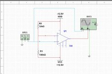
Here is a schematic that I drew up from memory and Aol=120,000. The standard method of find the Vref doesn't work. Vref = V*R2/R1 + R2. Then we have the output voltage: And another if Vin is 10Vp, which input voltages will have positive max outputs? I'm pretty sure voltage gain in the comparator = Aol. I can't recall what all the answer groups were.
I tried simulation, but got very different answer using AC input and Function Generator and still can't figure it out.
It's a real pisser.
Cheers
Funny, but you *should* have disclosed the full information from the beginning instead of sending us on a wild Math chase all over the place. FWIW even "1V" is NOT the exact answer, just "the less wrong" one..
We were thinking fractions of 1% differences while the actual question was "choose between approximate answer and gross 200% , 400% and 800% errors"
Oh well.
Thank you, but I didn't have access to the full information until I wrote the question and the answer groups. Doing the best that I can.
This could have been a really great opamp class that I was looking forward to. It ended up my worst nighmare. He takes his test material from a different text book!
The guy is always right, even when it's wrong! I can only fight just enough not to **** him off too much or retaliation and failure still passing better then average, but the goal was 90% or better. but that is another story, If you get bored I've added a comparator question...oh the joy.
Where would you use a comparator with both VCC & VDD tied with negative feedback? Maybe I should look into Horiwitz/Hill "The Art of Electronics", or Sedra/Smith's "Microelectonic Circuits"
Cheers,
If you chose not to drop the course then I have no sympathy. Will answer your comparator question in March/April after it is no longer possible to turn in my answers and pretend they're your own. Not that YOU would do that, but your untrustworthy classmates are doubtless reading this thread.
If you chose not to drop the course then I have no sympathy. Will answer your comparator question in March/April after it is no longer possible to turn in my answers and pretend they're your own. Not that YOU would do that, but your untrustworthy classmates are doubtless reading this thread.
What are you talking about Mark?
In which part of the country do you live ? Maybe you went to some other kind of school? The kind that has have multi semester exams? Where it overlaps from either:
- Christmas to Easter
- Hanukkah to Passover
- Mawlid an-Nabi to Laylat al-Mi'raj
I am, if it pisses you off so be it.
That is why I went back to college to learn about this. Community Colleges are supposed to fill this role for adult learners.
My biggest weakness was an understanding of solid state devices. You can look at stuff until you are blue in the face but it's damn hard to understand with out some training and education in it. So, I had to go through DC, then AC, then Solid State Devices, then OpAmps.
I ask these question after the test, to learn. I don't want to wait a week as with the OP. In this case I'll never see the instructor again and this was the last of the series of electronics classes.
This is the only guy who teaches the course at the CC. He's an adjunct instructor. Now to proceed.
I've not found a text book with it in it. I don't have a problem with a standard comparator, but this isn't something I've ever seen and I don't have a textbook in my library that shows it, that I've found.
That is the one that stumped me on the final exam and we never covered it in class. 5 total questions about it. First was ID it as a comparator, which I did. 4 more, I'm not sure about. If I had a correct answer, I changed it I think.
I'll never get the test back only get a score....
I didn't find the circuit in either of those texts. But I don't have 3rd ed nor 4th ed of H.H Art of Electronics but do have first ed and 2nd ed. Sedra/Smith is 5th ed. Other's are Grobs Basic Electronics 11e Floyd's, electronic devices, 9th ed. Paynter's Introductory Electronic Devices and Circuits, 3rd ed. Electronics Technology Fundamentals, 2nd ed. Boydell. Electronic Design, 2nd ed. Savant. Linear ICs for Technicians, 1st ed. Dungan. And the list goes on...to more advanced texts and some old physics texts and specialty texts.
Woops, I forgot to upload the schematic.
The output of the function generator is completely different than a simple AC sine input.
Cheers,
Attachments
Last edited:
I'm in the process of trying to recreate this Comparator question. It's one we haven't seen before, but it was on the final that I just finished.
Here is a schematic that I drew up from memory and Aol=120,000. The standard method of find the Vref doesn't work.
Vref = V*R2/R1 + R2.
Looks like you forgot the brackets - V*R2/(R1+R2) for a potential divider which assumes R2 is connected to GND typically. Which you haven't got on the schematic but you can still use the same equation. Just pretend that the -12V is GND and then at the end compensate for that sleight of hand.
With the VDD = GND then VCC becomes +24V. Then you get 24*12/(100+12) = 2.57V. The 'fix' at the end is to realize that this 2.57V is more positive than VDD at -12V so add it to VDD giving -9.43V. That's the Vref I presume.
Next up the Aol for a 741 is strongly frequency dependent so the gain of the 'comparator' depends on frequency, descending at 6dB/octave above the corner freq. If you go by TI's datasheet the corner frequency is around 3Hz and the Aol = 106dB (200,000) but that's with a 2k load. If you're only feeding a 'scope the gain will be higher.
Abraxalito,
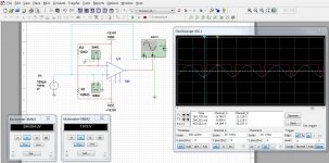
I calculated with the brackets...just left them off here I think...it was late. Here are two full simulations of the circuit on the scope. Now, let me read what you wrote.
I think I got that -9.43 also, but wasn't quite sure how. I thought originally output would swing from -11V to +11V. But somehow I think I changed Vout and got the 0 to +11V swing. Voltage gain I thought = Aol and had 120,000
Cheers,
Attachments

Last edited:
XMM1 is showing a Vref very close to GND so something's looking wrong....
The "~" button is blue. Could that mean AC volts?
Ah yes - good catch. And also I've now noticed I misread the oscillator output, which is 10V peak, not peak to peak. So yes there is enough swing to trip the 'comparator'.
I reckon the voltage gain for 1kHz will be around 60dB (1,000) and so you'd need at least 10mV to swing the output to the rails.
I reckon the voltage gain for 1kHz will be around 60dB (1,000) and so you'd need at least 10mV to swing the output to the rails.
Last edited:
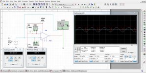
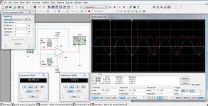
Comparator Vs is AC and Vs is Function Generator
I placed this with both side to side so they are easy to click and review. I'm still not sure why they are so different with what should be the same inputs.
One using an AC source the other an FG source. Everything else is equal.
I recall reading that w/o feedback referenced to output, the voltage gain (Av) = (Aol) Open Loop gain even though the device is actually limited by the supply voltage.
Color is what I chose to make them look different so they show up on the scope better.
AND, the function generator is not correct. It's cranking out 20 Vp-p NOT 10Vp as specified.
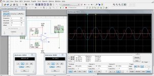
Okay here it is with FG set to 5Vpk
Cheers,
I placed this with both side to side so they are easy to click and review. I'm still not sure why they are so different with what should be the same inputs.
One using an AC source the other an FG source. Everything else is equal.
I recall reading that w/o feedback referenced to output, the voltage gain (Av) = (Aol) Open Loop gain even though the device is actually limited by the supply voltage.
Color is what I chose to make them look different so they show up on the scope better.
AND, the function generator is not correct. It's cranking out 20 Vp-p NOT 10Vp as specified.
Okay here it is with FG set to 5Vpk
Cheers,
Attachments
Last edited:
The second image is showing an input voltage going beyond the common-mode input range of the 741. All bets are off then as simulators are unlikely to handle erroneous circuit conditions in the same way as the real silicon. Some opamps exhibit phase reversal of the output under such conditions for instance.
- Status
- This old topic is closed. If you want to reopen this topic, contact a moderator using the "Report Post" button.
- Home
- Member Areas
- The Lounge
- Low Filter Roll Off Calculation