Use more plastic in the next one?
The fill was cubic ( I think ), and probably 10%. I'd have to check the slicer settings for the outer layer thickness, and that computer is back at the lake. I think I used the next to lowest layer height.
In version two of the jig, I added in some extra rigidity for the front panel. Hard to tell from the pics, but even that thick front panel with the side supports is a bit curved - the pics actually make it look better than it is ...
I had the windows in the car vented probably 100mm, and the car in the shade.
Finally got my miniVNA from China via DHL, arrived 5 days after I placed my order, shipping was free, or at least included with the price. I still have to mess around with it but it seems very promising. It includes SMA cables and terminations for OSL calibration.
Seems to be a Chineese copy of the original miniVNA from mini Radio Solutions, but for the price it is ok, and seems to be really well made.
This one measures from 100KHz to 200MHz, there's another version that goes from 1MHz to 3GHz which I'll buy in the future for my microwave amplifiers. Besides measuring antennas, I would like to measure transistor S parameters, filters and I'm really interested on measuring crystal motional parameters, I already have an old Saunders Crystal Impedance meter that I bough on e-bay a few years ago, but I would like to see how this VNA compares to it.
The only thing I don't like about PC based equipment is that it has an expiration date, either the software stops being compatible with the unit or the PC, or it just becomes obsolete, the company disappears, etc... A good stand alone VNA will last for a life time, some of the old HP VNAs are still being used today and the resale value is considerably high for a 30+ year old piece of equipment.
Last edited:
Use more plastic in the next one?
The fill was cubic ( I think ), and probably 10%. I'd have to check the slicer settings for the outer layer thickness, and that computer is back at the lake. I think I used the next to lowest layer height.
In version two of the jig, I added in some extra rigidity for the front panel. Hard to tell from the pics, but even that thick front panel with the side supports is a bit curved - the pics actually make it look better than it is ...
I had the windows in the car vented probably 100mm, and the car in the shade.
I never use less than 20% fill, and 50% or so if it needs some strength... Must have got quite warm though!
I had some cases for a work project I printed - were good for checking fit and my prototypes. Then it's easy enough to send the stl files to a commercial printer, I had them done for customers in high density nylon on an SLS machine, excellent results and very strong. Wasn't expensive.
I spoke with the folks at push plastic about the situation, and came back with a kilogram spool of this stuff:
Push Plastic High Heat PLA 3D printer filament
which may solve the temperature issue, although the color palette for this stuff is pretty bland. I got a spool of the silver ( light grey ) to try out.
I have not made any progress at all on the rig - I am still bogged down implementing CW. So far, I have not found any published DIY applications of this SG-9 board. The only non Mizuho commercial applications I have found using this board are in two Dentron radios - the channelized commercial rig that I have parted out for this rig, and another single band ham rig that never made it into production before Dentron folded up. Both were SSB only.
Studying the schematic diagram that Mizuho published for their 6 meter and 2 meter rigs that use their SG-9 board as the IF, it appears they had their rig transmit CW by closing the PTT switch ( in CW mode, this shifts the carrier oscillator 700 ish Hz during TX ) , and then to actually transmit RF CW, the morse key, when closed, closes the ground connections on the TX driver and PA to energize them, and pass RF to the antenna. They show the key jack as a shorting jack, so for SSB use, the key would be unplugged, so the PTT switch works everything for SSB.
In summary, a multi step process: unplug microphone or zero the TX audio gain ( otherwise any sound the mic picks up will modulate the shifted carrier oscillator - wouldn't that sound weird ) plug in the code key; set mode switch to CW; close the PTT switch to turn on the SG-9 TX ( so you need another separate PTT switch ), then close the key to send CW. This would be pretty easy to implement, but it just seems really Rube Goldberg awkward. On the other hand, how often do you use CW in your car while driving down the road? I haven't done it since college ...
It *might* be possible to double use the key to also ground the PTT line, but if that carrier oscillator is not dead on frequency and stable as soon as the shift is applied ( unlikely, I think ) it'll chirp. Mizuho did not do it this way, and I suspect chirp is why they didn't.
It might be easier to just key an audio tone into the mic circuit. The oscillator would have to be low distortion because the second and third harmonics are in the TX passband, and they would have to meet that same -30 dB or -40 dB standard as any other spur, depending on the power output.
So I'm still wrestling with how to do CW; it's a little more complicated than I thought it would be.
Last edited:
Finally got my miniVNA from China via DHL, arrived 5 days after I placed my order, shipping was free ...
I'm still waiting on four ( 4 ) orders I placed back in the first few days of May. I'm beginning to doubt they will ever arrive.
A couple of them are for different color/background of the 1602 type LCD's. One order is for a 3d printer - I got tired of waiting on it and just sourced a replacement printer from here in the states.
Is your stuff coming from China? where did you order it? I used aliexpress.com, never had any issues, not like e-bay, every time I order something from China on e-bay it either takes forever to get here or it never arrives.
Yes, China via AliExpress.
I'd like for the small orders to show up pretty soon since I want those LCD's for this project. I'm indifferent about the printer now that I have replaced it.
The trick when ordering from China is paying the extra $5 or $10 for shipping, the Free shipping that all merchants use is garbage, it will arrive 4 months later or will not arrive at all.
I got one of these "Nano VNA's" last week.
NanoVNA-H Portable Vector Network Analyzer 10KHz-1.5GHz MF HF VHF UHF Antenna | eBay
I can confirm that it works as expected with a few known loads that were lying around. I have an HP 8753C, but it is rather impractical for some outdoor antenna experiments. I will do a comparison between the large, heavy and expensive HP and the $80 handheld unit in a couple weeks when I get back from a road trip.
I got one of these "Nano VNA's" last week.
NanoVNA-H Portable Vector Network Analyzer 10KHz-1.5GHz MF HF VHF UHF Antenna | eBay
I can confirm that it works as expected with a few known loads that were lying around. I have an HP 8753C, but it is rather impractical for some outdoor antenna experiments. I will do a comparison between the large, heavy and expensive HP and the $80 handheld unit in a couple weeks when I get back from a road trip.
Try using the software Nano VNA Saver
Geez. I suppose for the price I could work with an upper limit of 1.5gHz. If I get a 5G design job I'll have to look for something else.
Seeing that I start to wonder how Agilent/Keysight/Tek/whoever-they-are-thesedays stay in business.
Just saw a Keysight PNA on e-bay for $380,000 used!, the thing can go up to 65GHz but still you can buy a house with that!
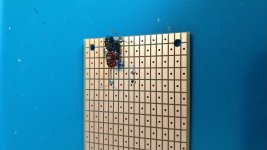
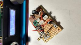
... The tiny Inductors are Murata LQW18A series High Q 0603. (those that look blue-ish.) The shortwave inductors are 1210 or 18?? from Coilcraft or EPCOS/TDK. They are not yet on the board.
I am not geting satisfactory results using SMD inductors in HF filters as constructed on these SMD prototype boards. I'm guessing that at some frequency the pads are going to have undesirable stray capacitance to ground, but it dosn't seem to be an issue at HF ( so far ). I'm doing something wrong, but I don't know what it is.
I built a chebyshev 3 pole low pass filter, - 3 dB cutoff predicted to be 30 MHz. In fact, the same low pass filter built point to point on the perforated board in the early up conversion experiments, so a known to work filter. I built it with 0805 ceramic caps, and the generic 0805 cheap china inductors that can be seen in the picture. I terminated each end with a 47 ohm 0805 resistor to force an impedance match. The calculator is at wa4dsy.net
As measured with the RP, the result was dismal. It had a low pass characteristic, but nowhere near what the filter program predicted, the roll off began about 10 MHz early and was very weak, even by three pole standards, really just a gentle slope. To eliminate the crap cheap china generic inductors as the problem, I built another with good quality EPCOS/TDK inductors ( surplus, but from a reputable vendor - I'm sure they are genuine parts ) but the results were still terrible. Better, but still terrible.
I removed the Epcos inductors, and subtituted inductors I wound on T-25 (red) cores, and remeasured. The 30 MHz predicted -3dB cutoff measured at 28.75 MHz. The program predicted -10 dB at 40 MHz, and I measured -15 dB. 50 MHz was predicted as -15 dB and I measured - 20 dB. I could probably tweak the toroids to get -3 dB at the predicted 30 MHz, but the point is that the toroids work, the SMD parts don't, and I don't understand why or what I am doing wrong.
So far I've fooled around with molded conformal inductors, SMD parts, and toroids, and the only thing that works as predicted in a filter circuit are toroid cores. As I've stated before, I'm aware of Q, but am not going to pretend I understand it. I would have expected the Epcos parts to be sufficiently high Q, maybe not like a toroid, but good enough to behave in circuit somewhat like predicted.
I think I am about ready to join the starter VNA club. I can't find anyone stateside that sells the VNA module for the Red Pitaya, so I may get one of the nano vna's. It seems there are several different variants of those.
Attachments
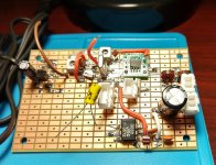
While I figure out the CW keying thing, I decided to build a fast and simple medium wave broadcast band receiver. Since the transmitter test jig has a very wide range, if mediocre, oscillator and power supplies available, it made sense to use it as the base.
This receiver strip is a rebuild of the early up conversion experiments, without all of the drama, from the beginning of this project.
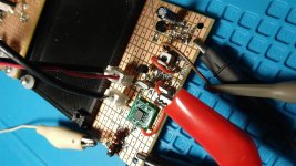
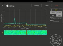
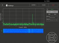
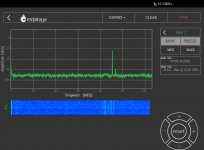
The front end is a simple three low pass filter good to about 28 MHz. The mixer is an SA602, the input is single ended, the output is sort of balanced through a tuned circuit. The mixer noise is probably the upper frequency limit of the strip. The transformers are those nominal 0.2 microhenry transformers we discussed back whenever. The xtal filter is one of the 7.5 Khz two pole ECS monolithic devices. The first picture is the mixer output tuned to a local broadcast station with about twenty feet of wire for the antenna. About the only thing the RP can see at the IF is the modulation peaks. The LO bleed through predominates. Recall the LO is coming into the board at - 2dBm to simulate the xvtr board output for building TX strips.
The IF is an NXP BF1105R dual gate MOSFET. This is an unusual device in that it is an enhancement mode device, and has all of the biasing components on the chip. It is very easy to use, so far I have only smoked one of them. It is a low voltage device, with a max Vds of 7 volts. They're serious about this spec ... . As of a few days ago, Mouser was still selling them.
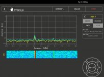
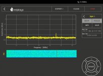
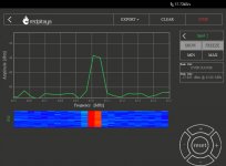
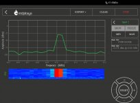
The red wire coming in separate from the test jig is from an adjustable power supply so I can see the gain response to get the AGC right. It looks like 2.7 volts on gate 2 is about max gain, and gain decreases as gate 2 voltage decreases. I can't tell how much gain the IF has. Before the BF1105, all the RP could see were the modulation peaks; after the BF1105 the station carrier is sitting at a solid -65 dBm. I am using 5 volts on the drain. The extra tuned circuit has eliminated the LO bleedthrough. Pictures 2 and 3 are the wide and narrow view of the IF output, respectively.
I will hang an SMA connector off the IF to use with the RP for newbie SDR.
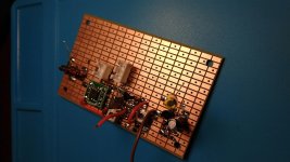
The transformers are tunable, but I don't have and can't find a diddle stick to fit the slugs. They could be tuned to resonance with a trimmer cap, and I have suitable SMD trimmers, but I measured one of them as they come out of the strip, and picked a capacitor to resonate at 45 MHz. I used the Si5351 and the peak hold feature on the RP to sweep the IF from 44 to 46 MHz and I got it almost dead on resonant at 45 MHz. It looks like the usable low frequency response of the rcvr will be in the range of 150 Khz. I believe these transformers are ham diy usable for both 6 and 2 meter tuned circuits.
The stuff at the end of the board is a try at a transistor infinite impedance detector. It may or may not work. It didn't work when hooked to the mixer output, but that may have been because there just wasn't enough RF there to demodulate.
If it works with the IF output as is, I may leave it alone, add an AGC amp and an LM386 and call it done. Or I might add another IF stage, and / or a down conversion. There is as lot of room left on the board.
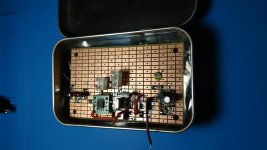
A lot of folks seem to package simple stuff in altoid cases. I find them very useful for safe storage and transport of these 50 x 80mm breadboards when they are not in use.
This receiver strip is a rebuild of the early up conversion experiments, without all of the drama, from the beginning of this project.
The front end is a simple three low pass filter good to about 28 MHz. The mixer is an SA602, the input is single ended, the output is sort of balanced through a tuned circuit. The mixer noise is probably the upper frequency limit of the strip. The transformers are those nominal 0.2 microhenry transformers we discussed back whenever. The xtal filter is one of the 7.5 Khz two pole ECS monolithic devices. The first picture is the mixer output tuned to a local broadcast station with about twenty feet of wire for the antenna. About the only thing the RP can see at the IF is the modulation peaks. The LO bleed through predominates. Recall the LO is coming into the board at - 2dBm to simulate the xvtr board output for building TX strips.
The IF is an NXP BF1105R dual gate MOSFET. This is an unusual device in that it is an enhancement mode device, and has all of the biasing components on the chip. It is very easy to use, so far I have only smoked one of them. It is a low voltage device, with a max Vds of 7 volts. They're serious about this spec ... . As of a few days ago, Mouser was still selling them.
The red wire coming in separate from the test jig is from an adjustable power supply so I can see the gain response to get the AGC right. It looks like 2.7 volts on gate 2 is about max gain, and gain decreases as gate 2 voltage decreases. I can't tell how much gain the IF has. Before the BF1105, all the RP could see were the modulation peaks; after the BF1105 the station carrier is sitting at a solid -65 dBm. I am using 5 volts on the drain. The extra tuned circuit has eliminated the LO bleedthrough. Pictures 2 and 3 are the wide and narrow view of the IF output, respectively.
I will hang an SMA connector off the IF to use with the RP for newbie SDR.
The transformers are tunable, but I don't have and can't find a diddle stick to fit the slugs. They could be tuned to resonance with a trimmer cap, and I have suitable SMD trimmers, but I measured one of them as they come out of the strip, and picked a capacitor to resonate at 45 MHz. I used the Si5351 and the peak hold feature on the RP to sweep the IF from 44 to 46 MHz and I got it almost dead on resonant at 45 MHz. It looks like the usable low frequency response of the rcvr will be in the range of 150 Khz. I believe these transformers are ham diy usable for both 6 and 2 meter tuned circuits.
The stuff at the end of the board is a try at a transistor infinite impedance detector. It may or may not work. It didn't work when hooked to the mixer output, but that may have been because there just wasn't enough RF there to demodulate.
If it works with the IF output as is, I may leave it alone, add an AGC amp and an LM386 and call it done. Or I might add another IF stage, and / or a down conversion. There is as lot of room left on the board.
A lot of folks seem to package simple stuff in altoid cases. I find them very useful for safe storage and transport of these 50 x 80mm breadboards when they are not in use.
Attachments
-
 altoids storage.jpg113.3 KB · Views: 67
 -
 board 2 (2).jpg160.8 KB · Views: 59
 -
 board 2 (1).jpg132 KB · Views: 58
 -
 45 MHz IF response.jpg77.5 KB · Views: 138
 -
 45 MHz BF1105 IF zoom view.jpg81 KB · Views: 144
 -
 45 MHz BF1105 IF wide view.jpg79.8 KB · Views: 142
 -
 45 MHz mixer output.jpg79.8 KB · Views: 152
Last night I put together a '386 amplifier, and tested it with the RP this morning to make sure it works properly. It seems to. It is set for the default 20 dB gain. It is not on the data sheet, but I have read these things can be run up to almost 80 dB gain by bypassing pin 1 or 8 ( can't remember which ) to ground with about 10 uF.
I cut most of the legs off the '386 so it doesn't look like it is on stilts. The output cap is awkwardly placed and needs to move to the left a little. The big open void in that area of the board was left for the (very) remote possibility of using the '386 to drive some bigger output transistors.
While building the little '386 amp, I discovered I had forgotten to solder the ground lead on the secondary of the last xfmr. Correcting that error increased the gain of that stage about 20 dB. The spec sheet says the BF1105 is good for nominal 38 dB gain at 200 MHz. I think I am getting close to that, maybe even a bit more. Sure beats a 40673.
Next step is to test the detector. I expect it will work okay.
All I want from this diversion is to comfortably listen to local broadcast stations, maybe VLF and some of the stronger lower frequency shortwave stations with just 4 to 7 meters of wire for an antenna, no drift, decent AGC, decent selectivity, and audio quality that doesn't make you want to drive nails into your ears after an hour or so, on a board that can plug in to the test jig when it is not being used for other stuff. So, very modest objectives.
That 51S-1 on my desk works very well and sounds quite good, but makes more heat than I care for in the summertime. The 6BF5 audio output could probably fry an egg it runs so hot. It can't easily be changed to anything else because of the series / parallel filament strings.
Attachments
I'm still waiting on four ( 4 ) orders I placed back in the first few days of May. I'm beginning to doubt they will ever arrive.
A couple of them are for different color/background of the 1602 type LCD's. One order is for a 3d printer - I got tired of waiting on it and just sourced a replacement printer from here in the states.
Well I'll be darned. The mailman just dropped off the 3d printer at my office. No sign of the other orders, but maybe they will eventually show up.
Yeah, the air express shipping I paid for took 47 days to get to LAX, and then two days to get from LAX to my front door, one of which was a Sunday ...
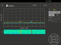
My IF is offset slightly high of 45 MHz. I found a small jewelers screwdriver that looked like it might be able to tweak the slugs in the transformers ( I know, I know, nobody needs to say anything ). Faced with the prospect of dialing in the coils with trial and error capacitor tweaking in a real crowded space, or the screwdriver, I VERY CAREFULLY used the tiny screwdriver and peaked the coils at 45 MHz. You can tell when the cores are moving because they make this agonizing creaking sound as they move. Mercifully, they didn't have to move much. If I had the stones to tune back and forth a bit ( I don't ) I might be able to get a bit better, but I didn't press my luck for fear of snapping a core.
I brought the signal strength up quite a bit, but it is still offset high of 45 MHz. I don't know what is up with this. ( edit: could the xtal filter be off frequency ? )
I removed the detector circuit, so I can relocate it to a better place on the board, freeing up space for a down conversion if I decide to do that. I put an SMA connector on the IF output to directly feed the RP. The pics are direct input to the RP. There is still a bit of LO bleed through. These SA602 are some eBay china chips, so I may replace it with a known genuine SA602 to see if that makes any difference.
Pics 1 and 2 are pre peak of the coils, pics 3 and 4 are post peak. I inadvertently used a different scale for the post peak pics, but if you look at them, you can see a significant ( 6 dB ) increase in the IF signal.
Attachments
Last edited:
I moved the detector next to the audio amp where it belongs, and have successfully received medium wave stations, but the performance is unsatisfactory.
First, everything is offset downward 10 KHz. The RF transformers are for sure peaked at 45 MHz, the LO is on frequency ( measured with two different instruments ) , so I can't see a reason for this offset other than the xtal filter being not quite right. Suggestions welcome.
The detector works, but the output is really weak. I may have made a bad transistor choice ( PN2907 edit: mmbt2907 ) since I considered this an audio circuit, rather than a low VHF RF circuit. And / or it may be ( probably is ) still insufficient overall RF gain. I figure I have about 50 dB net RF gain, at most, between the low pass filter and detector. The transformer is hung off the end to make it easier to change IF frequencies if I decide to do that.
I'm not sure if I want to add the additional RF gain at 45 MHz, or some other frequency. I have crystals to down convert to 10.7 MHz, 9 MHz, or 455 KHz, so all of the common low frequency IF's are available. I don't know that it makes any difference to the Red Pitaya in terms of what IF frequency it uses.
So, anyway, works but needs more work. I'll load up the travel kit with some parts relevant to this project, but this is really low priority - still need to resolve the CW situation to finish the other thing. I need to build a microphone or an adapter for an existing one, and it could be on low power SSB today.
Attachments
Last edited:
- Home
- Member Areas
- The Lounge
- No RF gear here?