No joy with the Baofeng chips - could not get them to draw any current, so for now, I seem stuck at a couple of milliwatts. It's a decent couple of milliwatts, the MMIC adds very little second harmonic, but just a couple of milliwatts.
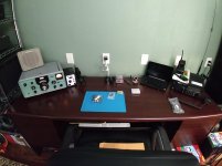
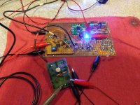
I cleaned off a desk for some light soldering at my office - the Red Pitaya is in the center, flanked by a general coverage receiver and VHF / UHF rig. I can't get it to connect to my wireless network here at the office, and the little netbook on the desk lacks an ethernet port for a direct connection, so somewhat of a dilemma. I'm using the specified dongle, which the RP recognizes, and it sees my network, but it won't connect.
I never cared much for linux, or any of its flavors. Hope I don't have to learn it. I suppose I could bodge / force a link by plugging the RP into an old wireless router, and connecting the netbook to that. I'm sure I have one here, somewhere.
Win W5JAG
Attachments
... That audio input transistor can NOT be a 2N4126, as that is a PNP. THINK it likely a 2N5172 ...
2N4124? Was / is a pretty common NPN general purpose transistor.
Win W5JAG
2N4124? Was / is a pretty common NPN general purpose transistor.
Win W5JAG
Very possible. I know designer was also fond of them. I think error was mine when I coppied schematic. He used 2N4126 as RF stages in his previous design. Input on that used 2N5172. But I also have a low freq oscillator design of his that uses the 2N4124s. Both are 25v parts. The 2N5172 just has a bit hotter max gain. So is probably a toss up.
Doc
Coming into this discussion late, I'll offer upload of best stereo modulator circuit I have seen thus far on the web. (Have seen better on commercial units and one custom built by a friend back in the 70s, but I don't have those schematics.)
(I'm sure the purists here will have comments about which op amps are used.)
Doc
Interesting. Long ago at my job I designed a stereo encoder for an RF FM signal generator. Only the AF unit "made" it to this site, with complete description, circuit diagram, PC layout. Those who don't understand German will have to use online translation.
FM-Stereo-Coder
Interesting. Long ago at my job I designed a stereo encoder for an RF FM signal generator. Only the AF unit "made" it to this site, with complete description, circuit diagram, PC layout. Those who don't understand German will have to use online translation.
FM-Stereo-Coder
Just to check, does the German system use the same sub carrier and pilot frequencies as the US? (38KHz, 19KHz) Just asking because I honestly don't know. I seem to recall the FM channel spacing was different in Europe. If so maybe affected subcarrier freq?
Doc
Never mind, I looked at it and they are the same.
Doc
Last edited:
Maybe they are lucky and don't have to deal with the SCA "channel". That is centered at 67 KHz from the carrier.
-Chris
Correct, SCA wasn't introduced in Europe where channel spacing could be as low as 100 KHz. That spacing already gave problems with FM stereo (requiring 200 KHz spacing) and SCA would have worsened that too much. That channel spacing also required close adherence to the modulation standard. Hence the FM radios I designed in Europe are of little use here in Panama, where you need at least 250 KHz per channel.
Has been a while since I was in radio, but I think the largest use of US SCA channels is probably for returning station telemetry. The Moseley remote controls used by most stations used a system of STL (Station Transmitter Link) up and SCA down. Meaning transmitter commands came to remote transmitter over SCA channel on signal from studio to transmitter and the transmitter readings were modulated over the SCA channel broadcast by the transmitter.
I once worked for a background music company (Elevator music) in the Salt Lake City market, which is a pretty busy FM market. At the time only two stations in the area were using SCA for other than telemetry applications. The background music was one, I think the other was a paging company. I guess to do so they had to make other provisions for station telemetry. (The station the background music was on had studio and transmitter at same location.)
Doc
Well, I think SCA has gone away now hasn't it? Now I hear that the digital information is affecting our sound quality. Too bad for people who use very good tuners here. My Revox B-261 doesn't seem to be affected. Other tuners might fare worse.
-Chris
The problem is caused by the stereo decoder. Ideally, a 38 KHz sine wave is generated from the 19 KHz pilot, and multiplied with the input signal. That results in AF from the 38 KHz side bands which with the LPF-ed input signal are fed to a matrix circuit to produce L and R. Such a decoder was immune to SCA and is immune to the HD side bands. It's cheaper to multiply with a square wave and thus arises the interference from the 15 KHz wide side bands of odd harmonics of 38 KHz. Various solutions have been used, best of all was by Pioneer. It used a digital demodulator (monostable) at 1.4 MHz and the pulse train was used to switch a (with the 19 KHz pilot locked) 38 KHz sine wave. Various articles at 88?108 MHz
Are LM1800s still available? Back in the days we used to upgrade our cheap FM receivers by installing an LM 1800 decoder IC.
Doc
Probably still available via eBay etc. In Europe I used the TDA1005A which could be used in TDM and FDM mode, the latter claiming 90 dB SCA rejection and also a lower distortion than TDM.
When I lived in Salt Lake City I got by just fine on my Technics ST-8077 AM/FM tuner or the built in FM on my Nakamichi RE-2 receiver. Where I live now in South West Utah it is not worth the bother. I only pick up two bad FM stations that are usually competing to play the same Beyonce song.
The two stations I pick up are so bad I actually looked into starting a low power FM station myself. (Which is why I happened to be looking into FM stereo encoder circuits.)
Between the FCC and ASCAP requirements I'm having second thoughts about the project. The FCC only issues LPFM lisences to "community organizations" or schools, not individuals or corporations. The ASCAP lisence for LPFM is only $154 a year, but specifically blocks album play.
Might be ahead building mp3 based solar powered disposable bootleg units and just tossing them out around the valley....
But the whole idea was to provide the area with a listenable FM station.
Doc
When I lived in Salt Lake City I got by just fine on my Technics ST-8077 AM/FM tuner or the built in FM on my Nakamichi RE-2 receiver. Where I live now in South West Utah it is not worth the bother. I only pick up two bad FM stations that are usually competing to play the same Beyonce song.
[...]
Doc
In Western Europe I have been living close to the borders with Belgium and Germany so could receive many stations. But one local station, AFN, produced 100 mV in a dipole which required a receiver with very good large-signal behavior. So I designed and built one (no varactor tuning of course) and could also enjoy stations from Denmark, East Germany, France, Luxembourg and the UK IOW always something nice to listen to. After emigrating to the Canary Islands (Spain) that receiver performed even better, providing good reception From Cape Verde, Gambia, Guinea-Bissau and Senegal. No commercials, much music (at the time) unavailable at record shops (no internet back then), one station was 24h/day and during the night played entire albums...
Attachments
Most impressive.
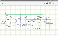
Here is the "other" FM wireless microphone schematic that my RF engineer friend designed. .This was the first one he gave me when I was complaining about just how bad a Radio Shack wireless mike performed. No question this beat the Radio Shack model hands down. Still not as stable as the other design I posted, but very acceptable. This one for sure uses the 2N5172 on input. Easy to overdrive so might add same 100k pot on input. As noted adjust C1 for frequency and C2 to peak signal. Sorry for the spresd out drawing. All I have is QuickCopper on my Android tablet to draw schematics on.
Doc
Attachments
Are LM1800s still available? Back in the days we used to upgrade our cheap FM receivers by installing an LM 1800 decoder IC.
Doc
You should be able to find some from a surplus house, and, of course, eBay. I used a house marked surplus MC1310 for the FM tuner I threw together back at post #86 in this thread. I think LM1800 has a couple of extra pins that makes things a bit less crowded than using MC1310.
I had MC1310 and LM1800 in stock in my junkbox; if I had to purchase a decoder chip from scratch, I would probably take a look at LM4500 ( I think ) since it has the stereo blend feature to reduce high frequency noise on weak signals.
It is described in the Nat Semi audio and radio handbook. The links to the last edition handbook are in one of the threads here in the lounge from a year or two ago.
I got a board ( to play with ) that used one of the cellphone type SDR FM chips, and I was shocked at how well it worked.
Win W5JAG
Most impressive.
Here is the "other" FM wireless microphone schematic that my RF engineer friend designed. .This was the first one he gave me when I was complaining about just how bad a Radio Shack wireless mike performed. No question this beat the Radio Shack model hands down. Still not as stable as the other design I posted, but very acceptable. This one for sure uses the 2N5172 on input. Easy to overdrive so might add same 100k pot on input. As noted adjust C1 for frequency and C2 to peak signal. Sorry for the spresd out drawing. All I have is QuickCopper on my Android tablet to draw schematics on.
Doc
Nice wireless mike, could be built in a matchbox. Long ago (working for Elektuur, now Elektor) I had to design a wireless mike plus receiver. Because the design had to conform to existing standards it was a bit more complicated. The receiver for it was a dual conversion type, first IF 10.7 MHz. This was the input for the TDA7000, an integrated FM receiver with low (70 KHz) IF and feedback FLL demodulator (feedback decreasing the required IF bandwidth).
Last edited:
I subbed in an LM3053 amplifier after the mixer. I didn't have a transformer that fit, so I tacked one to the back of the board for testing.
This seems to work pretty well, is a good match to the bandpass filter output without any additional matching, and doesn't require any special voltage considerations. For now it gives up broadband, but seems to be much more resistant to overload. I'm getting about 6 dB more gain than the MMIC, with identical drive, no stability problems as far as I can tell. Plus, there is a DC input to control the gain that might be useful, if I can figure out how to do ALC.
I have a bunch of MC1350, so might also try one of those in this position.
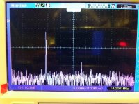
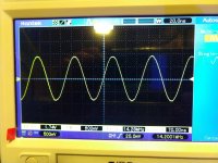
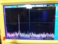
The kitchen table Red Pitaya screen shot is the spectrum analyzer program, it's looking at the output of one of the cheap eBay XR2206 based oscillators running at 1 KHz. The display is 20 Hz to 20 KHz. Looks like it will be a real useful device. Already thinking of buying a second one.
Five F1 tornado's here Saturday, and it sure looks like we could have more at any minute.
Win W5JAG
This seems to work pretty well, is a good match to the bandpass filter output without any additional matching, and doesn't require any special voltage considerations. For now it gives up broadband, but seems to be much more resistant to overload. I'm getting about 6 dB more gain than the MMIC, with identical drive, no stability problems as far as I can tell. Plus, there is a DC input to control the gain that might be useful, if I can figure out how to do ALC.
I have a bunch of MC1350, so might also try one of those in this position.
The kitchen table Red Pitaya screen shot is the spectrum analyzer program, it's looking at the output of one of the cheap eBay XR2206 based oscillators running at 1 KHz. The display is 20 Hz to 20 KHz. Looks like it will be a real useful device. Already thinking of buying a second one.
Five F1 tornado's here Saturday, and it sure looks like we could have more at any minute.
Win W5JAG
Attachments
- Home
- Member Areas
- The Lounge
- No RF gear here?