Deal, I see a tube in that box that I have been buying for about $10 each when I can find them.
I could have got just that one tube for $0.25 USD, but went ahead and got the whole box when I saw some 5V6 and 12BH7 in there ...
It had a good assortment of about 65 unused sweep tubes that had not gone to air, a half dozen that I had to toss out, about a half dozen NIB 12BH7, and maybe two or three dozen less interesting types.
I saw a lot of 50's vintage NIB JAN 1625, 6Y6G, and 807, but left those for someone else.
Win W5JAG
If the pirate could only get 3 miles on 17 watts, that's pretty good proof he knew nothing about antennas. I have worked every state in the US and several EU countries on 5 watts cw. And that is nothing special for a licensed radio op. FM or any other vhf circuit would be virtually impossible to design and build with no prior training or knowledge. You can buy a 5w FM chinese hand held for less than $50 new on ebay.
pirate could only get 3 miles on 17 watts, that's pretty good proof he knew nothing about antennas
He wasn't looking for a large range, and he didn't know much about RF, antennas, or electronics in general. His equipment was purchased online and installed by one of his friends. His antenna was barely above the roofline, so some added height would have helped if he wanted it. He played music, guitar lessons (simulcast online) and pretty much kept a low profile.
There was another high profile pirate who bragged that the FCC coudn't touch him. He ran several hundred watts, flew a 6 X 9 FOOT Pirate flag from his 100 foot tower, and had all sorts of controversial stuff on the air......he was right, the FCC did't touch him but the police (drugs) and the IRS (tax evasion) did........I think he spent a couple of years in the "hotel."
You can buy a 5w FM chinese hand held
I grabbed a Baofeng and a Radioddity GD-77 DMR radio cheap on Amazon when the rumors of banning them all first appeared. Of course there isn't a DMR repeater or access point within 50 miles of me, so it hasn't seen much use yet.
the Claremore hamfest, next week
Sherri and I were in the car headed for Florida and the Orlando hamfest when an unfortunate event forced us to turn around and go back home. I still plan to be at the hamfest called "Dayton" this year, even though it's not in Dayton any longer.
I have to go now, but I'll send you a PM later today or tomorrow. You might want to hang on to those sweep tubes. I have two projects in the works, one P-P and one SE to squeeze the most out of them. Tubelab stuff is kinda on hold right now, I have a contract job in the RF world to pay the bills for now.
... might want to hang on to those... two projects in the works, one P-P and one SE to squeeze the most out of them. ...
I can only imagine how many watts that must be. Those 20LF6's look good for 500 watts SSB, easy. That other tube has bigger plates AND wings on the plate for even more dissipation.
Win W5JAG
I see that in some higher level RF amps, some designers place a zener diode from the collector to ground; the zener device is several multiples of the operating voltage.
Is this a protection device to clamp peak to peak RF voltage to safe levels? Is this a desirable circuit addition? Will the diode junction generate any extra harmonic / spurious content?
I have been frying transistors and thought this might be a useful trick if it does not otherwise degrade the circuit.
edit: In FCC jurisdiction, it looks like the spurious limit for an *amateur* transmitter below 30 MHz is that the *combined* total of all harmonic / spurious content must be -43 dB relative to the mean output of the transmitter. It looks like I am still okay at the output of the MMIC following the bandpass filter, but don't want to add anything that can start generating non harmonic spurs.
Fortunately, we seem to be a little more lax than some jurisdictions.
Win W5JAG
Last edited:
The zener diode is an attempt to protect the RF output device from high collector voltages caused by a mismatched load. A high VSWR at the right phase angle can put 75 volts or more on the collector of a 12 volt RF amp.
Any semiconductor device is a Voltage Variable Capacitor when operating in a reverse bias region. A VVC or varactor is a useful device for use as a frequency multiplier, and thus CAN generate harmonics, as does the base collector junction of the output transistor, so there is usually a low pass filter incorporated into the matching circuit.
I once made a "cloaking device" by modulating a 2 watt 900 MHz transmitter with AM and FM noise, then applying its output to a parallel string of ordinary 1N914 diodes which were mounted in a cavity made from PC board material. The efficiency was somewhere between zero and nothing, but there was enough broadband noise output at 10.5 GHz to cause a moving object to be "invisible" to a radar device attempting to measure its velocity. This was about 25 years ago and I don't remember the details but I do believe that some DC was applied to the diodes.
this might be a useful trick if it does not otherwise degrade the circuit.
Any semiconductor device is a Voltage Variable Capacitor when operating in a reverse bias region. A VVC or varactor is a useful device for use as a frequency multiplier, and thus CAN generate harmonics, as does the base collector junction of the output transistor, so there is usually a low pass filter incorporated into the matching circuit.
I once made a "cloaking device" by modulating a 2 watt 900 MHz transmitter with AM and FM noise, then applying its output to a parallel string of ordinary 1N914 diodes which were mounted in a cavity made from PC board material. The efficiency was somewhere between zero and nothing, but there was enough broadband noise output at 10.5 GHz to cause a moving object to be "invisible" to a radar device attempting to measure its velocity. This was about 25 years ago and I don't remember the details but I do believe that some DC was applied to the diodes.
If Red Pitaya, then the 14 bit version, that's where the dynamic range starts to get interesting. ...
Have you had a chance to play with the Red Pitaya?
I've been looking at the 14 bit device to use as portable test equipment at our second house, where I am spending more time. Or one of the multi function handheld oscilloscopes that are in the same price range. SDR function, the 14 bit dynamic range, and slightly lower cost, keep bringing me back to the Red Pitaya. I keep a laptop PC up there, so I would not have to carry that part with me.
I see they now have a 16 bit version especially for SDR, with 50 ohm inputs, but it seems like this would be less useful, or not useful at all, as a piece of test equipment, because of the low impedance inputs?
Win W5JAG
Not much. It is on the shelf 2 meters behind me collecting dust. I'm currently more interested into low noise amplifiers, choppers and a LTC2500-32 based digitizer driven by a BeagleBoneBlack. I have upgraded the Pitaya however from this exotic Alpine Linux to Debian that I'm more used to. No QSO in maybe 20 years.
50 Ohm inputs are quite OK. My spectrum / network analyzers, TDR, really fast scopes, noise figure meter, signal generators and whatever all have 50 Ohm. The right thing for Hi-Z measurements is a FET probe. After a meter of coax nothing is high impedance any more. I love that old HP1152A.
73, Gerhard
Mouser had three (3) of the 14 bit variants in stock, and none of the 16 bit, so a 14 bit Red Pitaya should be on it's way to W5JAG sometime later this afternoon or evening.
Indeed, although I am primarily getting it as a compact piece of test equipment to use on the kitchen table at the second house, I'm thinking of block converting a band to 45 MHz or wherever is convenient, and let the Pitaya tune the IF. In all modes.
SMD/SMT, SDR, FFT, maybe the 21st century isn't so bad.
Win W5JAG
... the Pitaya gets the 32 MHz difference. It helps tremendously that I can use every IF frequency up to 60 MHz. ...
Indeed, although I am primarily getting it as a compact piece of test equipment to use on the kitchen table at the second house, I'm thinking of block converting a band to 45 MHz or wherever is convenient, and let the Pitaya tune the IF. In all modes.
SMD/SMT, SDR, FFT, maybe the 21st century isn't so bad.
Win W5JAG
Last edited:
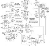
Coming into this discussion late, I'll offer upload of best stereo modulator circuit I have seen thus far on the web. (Have seen better on commercial units and one custom built by a friend back in the 70s, but I don't have those schematics.)
(I'm sure the purists here will have comments about which op amps are used.)
Doc
(I'm sure the purists here will have comments about which op amps are used.)
Doc
Attachments
My Red Pitaya was delivered Friday, and last night I installed it in the acrylic case. I'm not sure the aluminum box would fit in my toolkit.
Using a direct Ethernet connection, it connected without any difficulty to the Win 10 laptop here at the lake. I tried out one channel of the o scope function, and it seems to work.
Do I need the vector network analyzer stuff? What does a vector network analyzer do? More to the point, what would it do for me?
The pitaya fits perfectly in my travel box of parts / tools. The documentation, such as it is, seems half baked, but the device itself is pretty impressive at first look. Looking forward to playing around with it as time permits.
Win W5JAG
Last edited:
Congratulations!
My RP is still naked. BTW it has an ADC made by NXP; this is slightly higher than the Zynq and since there is a common heat sink for everything, the Zynq has less than optimum thermal contact. It was not even covered by grease really. I did match the heights with metal foil or a fiber thermal pad, I don't remember exactly. I also mounted a small fan above the sink, 40 by 40 mm and 19 mm thick. This is completely oversized; it even produces an unpleasant air movement on the table.
The vector network analyzer is the biggest thing since sliced bread. It is the combination of a signal generator and a selective voltmeter. With it, you can sweep filters and amplifiers.
It has 2 ports: port 1 and 2. Port 1 is the input to your filter, port 2 is the output of your filter.
Then, S21 (pronounced S-2-1) is the gain / loss. You get both the real part (magnitude) and the phase shift at the same time.
S11 is the input matching. The real part goes to zero for a perfect 50 Ohm match. It is possible to compute the input R, L, C, SWR etc as function frequency. In the case of
filters, S11 reveals design errors very easily. In the passband, there must not be a lot of reflection, but in the stop band there usually is. The signal power must end up somewhere and if it does not go through the filter, it must be reflected.
There are special filters called diplexers that may have internal load resistors. With these you can enforce a 50 Ohm input impedance, which is good for the IP3 of your preamp, even when its load, say a crystal filter, has impedance all over the place.
I think, RP can only measure S11 and S21. There are also S22 and S12. This is the output match and the gain in backward direction. If you want to measure it, you have to turn around the object.
I have a Rohde & Schwarz ZVB8 VNA, so I never really looked into that function of the RP.
Good weather here today; I must now take a ride on the motor bike.
Gerhard
I ran mine for about two hours last night, and it got warm, but not really hot. However, most of that time, it was not doing anything that would generate much work or heat.
The acrylic case has slots and mounting points for a 25 - 30 mm or so fan, so I will watch the temperature as I use it and get more familiar with it.
I ordered the specified wi fi dongle, so I can see how the RP works in a wireless setup. That should be here before the next weekend. My first impression of the RP is very favorable - I'm looking forward to learning how to use it. I had never heard of RP until it was mentioned in this thread ...
I got a junker Baofeng UV-3 for free ( TX works, no audio ), so I have harvested the broadband driver and PA chips out of that ( it appears to have separate TX strips for VHF and UHF, so I got four chips ) to experiment with. I have no idea if they will work at HF, but I would rather make my mistakes with free stuff before I move on to parts I have to buy.
I've had 2N3866 running in a crude broadband setup at around a couple of watts; they look good on the scope and FFT for a few minutes, and then the sine wave starts to tilt toward a triangle, and they just die shortly thereafter. I can't see anything obviously wrong, and they are within all specs, but I've killed several. I'm guessing I haven't got the ferrite load right, but I've fried almost all that I can afford to waste. For now I pulled all of that back off the board to try the Baofeng chips ....
Win W5JAG
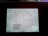
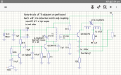
Okay, here is what I've got. One is a pic I took of schematic. The second is a quick drawing I did on quick copper on my tablet to clarify values. Good thing I did that as I discovered an error. That audio input transistor can NOT be a 2N4126, as that is a PNP. THINK it likely a 2N5172. Which I know the designer is fond of.
Odd looking caps on final are 1000pf feed through caps. Thermal coupling on C1 & Q2 is just a blob of epoxy between transistor case and cap body. Adjustment Caps aren't critical for range. 5-30pf would work. NPO is important for temperature stability.
Will find number of that input and post it. The others are correct.
I think you could use 1/8 w resistors. Electrolytics 16v. That 0.1 bypass on base of Q2 is just disk. Oh, as I recall coils were wound on 3/16 form or stick. That 10 ohm feeding final probably needs to be 1/4 or even 1/2 W
Doc
Attachments
Last edited:
- Home
- Member Areas
- The Lounge
- No RF gear here?