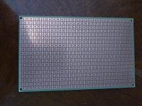
....Take a look at the bottom board in post #216. That is excellent
for RF work. You get a relatively ideal ground plane and attaching
components to GND takes just a solder blob on the top side.
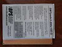
The bottom layer is just square pads. There is also a deluxe
version with plated-through holes. That makes the pads stick better
to the board, but the cheap version is usually good enough.
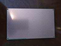
This was in the Mouser catalog, and is similar to what you are describing. The holes are not plated through, I felt it was more versatile if they are unplated.
This is the large size, almost identical to the piece of perf I have been using, with the largest pads. Since my SMD inventory is going to be thin for quite some time, I want to be able to use small through hole parts with the leads clipped short.
Attachments
I'm going to straddle the SMD fence for a while. These are probably not suitable for GHz level RF work, but probably OK for IF and audio.
My immediate application is for an analog music synthesizer, mixing SMD and through hole parts. It will combine SMD and DIP IC's with mostly leaded discrete parts and even a few vacuum tubes.
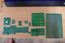
These SMD chip adapters come from Amazon as does the perf proto board.
The adapters have a SOIC pattern on one side and a SSOP patern on the other side. There are even QFP adapters with two different lead pitch. Each terminated in a row of holes on 0.1 inch centers for use with the perf board, or your favorite white plug in breadboard.
McIgIcM 30pcs PCB Board Kit SMD Turn To DIP Adapter Converter Plate FQFP 32 44 64 80 100 HTQFP QFN48 SOP SSOP TSSOP 8 14 16 20 28: Amazon.com: Industrial & Scientific
50pcs Top Quality Double Sided Circuit SMD PCB Convertion Board Module for TSSOP16 MSOP16 to In-line: Amazon.com: Industrial & Scientific
Uxcell a14062100ux0248 15 Piece SMD SOP24 SSOP24 TSSOP24 0.65 mm/1.27 mm to DIP 2.54 mm PCB Board Adapter: Amazon.com: Industrial & Scientific
Uxcell a16040500ux0190 3 Piece Double Sided Prototype Universal PCB Print Circuit Board 9 x 15 cm Green, 5.91" Width, 3.54" Length: Amazon.com: Industrial & Scientific
My immediate application is for an analog music synthesizer, mixing SMD and through hole parts. It will combine SMD and DIP IC's with mostly leaded discrete parts and even a few vacuum tubes.
These SMD chip adapters come from Amazon as does the perf proto board.
The adapters have a SOIC pattern on one side and a SSOP patern on the other side. There are even QFP adapters with two different lead pitch. Each terminated in a row of holes on 0.1 inch centers for use with the perf board, or your favorite white plug in breadboard.
McIgIcM 30pcs PCB Board Kit SMD Turn To DIP Adapter Converter Plate FQFP 32 44 64 80 100 HTQFP QFN48 SOP SSOP TSSOP 8 14 16 20 28: Amazon.com: Industrial & Scientific
50pcs Top Quality Double Sided Circuit SMD PCB Convertion Board Module for TSSOP16 MSOP16 to In-line: Amazon.com: Industrial & Scientific
Uxcell a14062100ux0248 15 Piece SMD SOP24 SSOP24 TSSOP24 0.65 mm/1.27 mm to DIP 2.54 mm PCB Board Adapter: Amazon.com: Industrial & Scientific
Uxcell a16040500ux0190 3 Piece Double Sided Prototype Universal PCB Print Circuit Board 9 x 15 cm Green, 5.91" Width, 3.54" Length: Amazon.com: Industrial & Scientific
Attachments
I have some SO8IC / SSOP adapters and some new to me RF chips to try out. I'm hoping the adapters will be OK for low VHF / HF. I also got some SMD versions of SA612, since I already have, and had been planning on fooling around with, leaded SA602/612.
I'm still waiting on some SOT-23 transistor adapters. I have some basic SMD RF JFET's and some general purpose JFET's ( J301 and J211 ? ), and the SMD equivalents of 2N2222, 2N3904, and 2N3906 to get started with.
I'm sure my stuff will look Frankenstein - ish. Hopefully it will work better than Doc Frankenstein's stuff.
I used the crude spectrum analysis function on the Hantek DSO to take a look at the output of that Si5351 synthesizer. I put the LO at 12 Mhz. I still have some concerns that I do not have a suitable first LO, be it for up or down conversion.
If I stick with the 45 MHz IF, I bought a bag of 18 Mhz crystals off eBay to make a crystal controlled second LO. The idea being twice 18 to get 36 MHz for one sideband, three times 18 to get 54 MHz for the other sideband. This should be cheaper than a second BFO crystal for the 9 MHz IF, and a lot cleaner than that Si5351 synthesizer.
I have another Si5351 in my Mouser shopping cart for my next order to see if that improves things; I feel like I can now handle replacing SMD stuff. If I botch it, big deal - I still have the QRP Labs thing or my PLL setup.
Win W5JAG
I didn't have a USB Stick, so these are just cheap cell phone shots of the Hantek screen.
These next few posts are some snapshots of the Si5351 output.
Each output has a fixed 10 dB 50 ohm attenuator ahead of the scope probe.
I reset the device before taking these pictures, so actual frequency will be off a bit as I did not recalibrate the crystal.
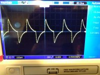
The first pic is the TUNABLE LO at 3.6000 MHz. The FIXED LO is set to 0 Hz, which should be OFF.
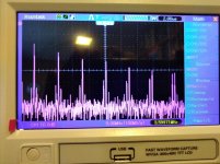
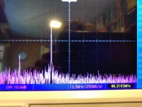
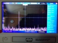
The second pic is the FFT of the tunable LO at the same frequency. Note the harmonic distribution, and the sidebands / spurs adjacent to the tunable LO and the harmonics.
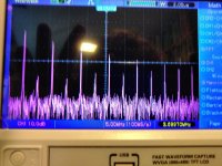
The third pic is the FFT of the tunable LO shifted about 100 kc from the original frequency. Note the spurs have moved about 2.5 MHz from their original distribution. As the tunable LO is moved around, these sidebands / spurs also move around, including back and forth across the LO.
I observed this behavior up to about 12 Mhz or so. As frequency increases, the sawtooth wave transforms to more of a square wave, and eventually sine waves.
Win W5JAG
These next few posts are some snapshots of the Si5351 output.
Each output has a fixed 10 dB 50 ohm attenuator ahead of the scope probe.
I reset the device before taking these pictures, so actual frequency will be off a bit as I did not recalibrate the crystal.
The first pic is the TUNABLE LO at 3.6000 MHz. The FIXED LO is set to 0 Hz, which should be OFF.
The second pic is the FFT of the tunable LO at the same frequency. Note the harmonic distribution, and the sidebands / spurs adjacent to the tunable LO and the harmonics.
The third pic is the FFT of the tunable LO shifted about 100 kc from the original frequency. Note the spurs have moved about 2.5 MHz from their original distribution. As the tunable LO is moved around, these sidebands / spurs also move around, including back and forth across the LO.
I observed this behavior up to about 12 Mhz or so. As frequency increases, the sawtooth wave transforms to more of a square wave, and eventually sine waves.
Win W5JAG
Attachments
This series of shots is with the synthesizer set to produce a 45 Mhz IF output.
The LO is tuned to a local broadcast station at 1.32 MHz, the module is set to ADD the 45 MHz IF, so the tunable LO will be 1.32 Mhz + 45 Mhz = 46.32 MHz, differing only by the error in the uncalibrated reference crystal.
The FIXED LO is set to 0 Hz, which should be off.
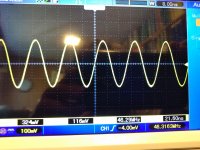
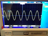
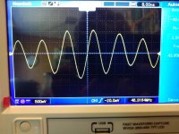
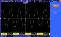
The first pic is a clean 46 MHz sine wave.
The second pic is the FFT of the 46 MHz sine wave. Not world class, but looks good enough to me.
The third pic is the FIXED LO which is supposed to be turned off. WTH? The tunable LO is present on this output, and look at the amplitude - about 12 dB stronger than the actual tunable LO. Both of these track perfectly - change the tunable LO 1 kc, the fixed tracks it.
Win W5JAG
The LO is tuned to a local broadcast station at 1.32 MHz, the module is set to ADD the 45 MHz IF, so the tunable LO will be 1.32 Mhz + 45 Mhz = 46.32 MHz, differing only by the error in the uncalibrated reference crystal.
The FIXED LO is set to 0 Hz, which should be off.
The first pic is a clean 46 MHz sine wave.
The second pic is the FFT of the 46 MHz sine wave. Not world class, but looks good enough to me.
The third pic is the FIXED LO which is supposed to be turned off. WTH? The tunable LO is present on this output, and look at the amplitude - about 12 dB stronger than the actual tunable LO. Both of these track perfectly - change the tunable LO 1 kc, the fixed tracks it.
Win W5JAG
Attachments
This series of shots is with the synthesizer set to produce a 45 Mhz first IF output, and the FIXED LO is set to 36 MHz to produce a 9 MHz second IF.
The first pic is with the scope on the output of the TUNABLE LO.
Note the scope clearly shows the presence of two sine wave frequencies. Note also that the scope is counting the FIXED LO frequency as the predominant frequency.
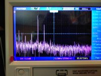
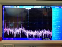
The second pic is the FFT of the TUNABLE LO with both outputs turned on. Note the FFT also shows the FIXED LO present at a stronger amplitude than the tunable LO, the increased noise floor, and other spurious signals. And this is just the first 50 dB or so. Who knows what other crap is below what can be seen with just 8 bits.
Win W5JAG
The first pic is with the scope on the output of the TUNABLE LO.
Note the scope clearly shows the presence of two sine wave frequencies. Note also that the scope is counting the FIXED LO frequency as the predominant frequency.
The second pic is the FFT of the TUNABLE LO with both outputs turned on. Note the FFT also shows the FIXED LO present at a stronger amplitude than the tunable LO, the increased noise floor, and other spurious signals. And this is just the first 50 dB or so. Who knows what other crap is below what can be seen with just 8 bits.
Win W5JAG
Attachments
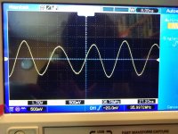
This series of pics is of the FIXED Lo output; again the tunable LO is at 46.32 MHz, and the fixed LO is at 36 MHz for a second conversion to 9 MHz.
The first pic clearly shows the presence of two sine waves. Note that the scope is counting the frequency of the TUNABLE LO, even though this is the fixed output.
The second pic is the FFT of the fixed LO output. Note that the tunable LO predominates over the fixed LO, the increased noise floor, and the other spurs in the FFT.
The crazy idea of putting a tuned circuit in the gate of the second mixer doesn't look as crazy now, and it did help, but it would never fix this mess.
Win W5JAG
Attachments
So, I now understand why I could produce a good enough to quite good conversion to a 45 MHz first IF, but could never produce a satisfactory conversion to a second IF of any frequency.
I probed around the mixers with a wavemeter, and probably should have caught this, but for whatever reason, I did not.
The idea of going to a crystal second LO to be able to switch sidebands should fix this, although without the new scope ( $203 WELL spent ) I would have had only gut feelings as to why.
I want to stick with this synthesizer module for the same reason I bought it in the first place - it is very small, and should lend itself to a compact control head. Since the fixed LO apparently cannot be turned off, I guess I will set it to 0 Hz and ground the output through a 50 ohm resistor. Or use it as the second tunable LO if I need more output, maybe for the TX side .....
I have no idea if this is how Si5351 normally work. It sure looks craptastic if it is. I have no idea whether this particular chip is flawed / damaged; the firmware is flawed, or some weird combination of both. I do have another Si5351 vfo from QRP Labs, but after six months of talk, and five months of soldering, I don't have the intellectual curiosity to find out the answer at this time.
I now sort of regret tearing down that DG MOSFET board - it probably would have worked quite well with a crystal controlled second LO.
Oh well.
Win W5JAG
eBay had another flash sale a couple of days ago, 20% off anything, so I picked up a 60 MHz dual channel arbitrary waveform generator, and a few other bits.
In the meantime, I have been playing with some LM375, a part so obscure and obsolete, I doubt a stand alone data sheet can even be found for it. But, I have a bunch of them, so, use what you got. It is in the 1970 era National Linear handbooks, and the first ( I think ) volume of the old ECG databooks. Google coughs up a few images that derive from an article on oscillators in Ham Radio magazine, and the actual article can be found with a diligent search. Unfortunately, the circuit(s) they published for LM375 will not work. The Ham Radio circuit got republished in a lot of the big circuit books of the time.
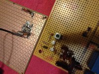
The pics are of a working LM375 - it looks rough because I had to rework it to make it work, and I'm still fooling with feedback values. This is basically the data sheet circuit. On paper, this device is good to 200 MHz. The tuned circuit is at 18 MHz - the temptation is to put the tuned circuit at one of the harmonics, but I doubt it will work that way, although I haven't tried it yet. The thought is / was to just use a separate LM375 and frequency doubler/tripler for each 2nd LO frequency. This one pictured is about 12 Khz low of where it needs to be. I haven't played with pulling the xtal around. These cheap microprocessor crystals may not be up to the task.
I haven't played with discrete oscillators yet.
With SMD an option, it looks like there are much better IC alternatives. I've attached a data sheet of one part, for comment if anyone has some. It indicates it can pull a crystal in both directions, probably better suited to these cheap crystals than the LM375. I wonder how frequency stable it would be in the heat around here.
I see that Mouser has some of the Crystek CVHD-950 oscillators, but only for 54 MHz. That only gives me one sideband, USB IIRC, so that could still be an option. I didn't see any other frequencies in their line that I could divide / multiply to get what I need.
Win W5JAG
In the meantime, I have been playing with some LM375, a part so obscure and obsolete, I doubt a stand alone data sheet can even be found for it. But, I have a bunch of them, so, use what you got. It is in the 1970 era National Linear handbooks, and the first ( I think ) volume of the old ECG databooks. Google coughs up a few images that derive from an article on oscillators in Ham Radio magazine, and the actual article can be found with a diligent search. Unfortunately, the circuit(s) they published for LM375 will not work. The Ham Radio circuit got republished in a lot of the big circuit books of the time.
The pics are of a working LM375 - it looks rough because I had to rework it to make it work, and I'm still fooling with feedback values. This is basically the data sheet circuit. On paper, this device is good to 200 MHz. The tuned circuit is at 18 MHz - the temptation is to put the tuned circuit at one of the harmonics, but I doubt it will work that way, although I haven't tried it yet. The thought is / was to just use a separate LM375 and frequency doubler/tripler for each 2nd LO frequency. This one pictured is about 12 Khz low of where it needs to be. I haven't played with pulling the xtal around. These cheap microprocessor crystals may not be up to the task.
I haven't played with discrete oscillators yet.
.... I choose a Crystek CVHD-950 100 MHz oscillator, that has quite
good phase noise, I wonder how they make it in that small package.
It is a VCXO, so I can lock it to an external 5/10 MHz reference in case
it is necessary. I double it twice to 400 MHz, ...
With SMD an option, it looks like there are much better IC alternatives. I've attached a data sheet of one part, for comment if anyone has some. It indicates it can pull a crystal in both directions, probably better suited to these cheap crystals than the LM375. I wonder how frequency stable it would be in the heat around here.
I see that Mouser has some of the Crystek CVHD-950 oscillators, but only for 54 MHz. That only gives me one sideband, USB IIRC, so that could still be an option. I didn't see any other frequencies in their line that I could divide / multiply to get what I need.
Win W5JAG
Attachments
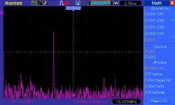
So, I cleaned it up a bit, and here is the result: spot on at 18.0000 MHz, second harmonic and a few other spurs all better than 40 dB down.
This is with a random crystal, pulled from a $2 eBay bag of 18.000 MHz crystals. If I could show the datasheet ( haven't found one online, but it is in the 1972 databook ) the circuit I am using is the VCXO series tuned oscillator, variable capacitance in series with the crystal, except I am using a trimmer instead of a varicap. This one is a bit sensitive to the quality of the trimmer - with a cheap ceramic trimmer, it looked dirty around the fundamental starting at about -40 dB, but with the better trimmer shown, the output looks good enough for a simple transceiver, unless someone sees something I am missing.
Seems stable - its ran on my bench with a fan blowing across it for about four hours, and has not moved. It's running at 14.4 VDC.
It occurs to me that if the tunable LO stays put, and with a fixed BFO frequency, then moving the second LO back and forth across the IF implements the IF shift feature of low end transceivers? I have plenty of varicap diodes, I didn't use one because I thought it might compromise stability.
These crystals are almost as cheap as dirt, so I ordered a couple of bags of 36 and 54 MHz crystals to try out. Maybe a doubler or tripler won't be needed.
As an aside, I have the hard copy of this book, but found a link to it online:
https://bgaudioclub.org/uploads/docs/Crystal_Oscillator_Circuits_Krieger_Matthys.pdf
It has a couple of pages on LM375, which also look to be wrong as evidenced by the FFT shown here, but it does have a lot of good information on oscillators.
Win W5JAG
Attachments
OP: In Melbourne it's worthwhile tuning in to Crossband Radio, which has been in operation around 40 years on the ham bands. They've skirted the law and played cat-and-mouse with the radio inspectors for most of that time. Most 'taining indeed. You can find recordings of some of their older 'missions here:
ONE SIXTY METER CROSSBAND RADIO
ONE SIXTY METER CROSSBAND RADIO
Last edited:
In New Zealand I met an old pilot called Bob who spent many years doing parcel deliveries to tiny Pacific islands. At one stage he was semi-retired and decided to set up a pirate radio station on the island he was living on. Before every raid he would get word that there was an inspector arriving, just in time to shift the antenna to a different tree.
But Bob got bored and when he heard of a new arrival who owned a nice little French airplane he decided to make a new friend in the hope of getting a bit of flying in. After establishing his flying credentials the owner was happy to let Bob take it up, and elated he shot off into the sky and familiarized himself with the controls. The little plane handled quite differently than Bob was used to and was quite slick, so he spent a fair bit of time doing simulated landings at altitude to ensure he wouldn't overshoot the island's rather small runway.
About this point he realized that he had lost sight of the island. Looking at the gauges and instruments he also realized that most of them were in French, and that navigating back to his point of origin was going to be trickier than expected. After considering his plight for a while he struck on a solution. He retuned the radios to pick up his pirate radio station and used it as a homing beacon.
True story.
Last edited:
I put the tuned circuit at 54 MHz, and it would not oscillate. I didn't try very hard to make it work, since I have more crystals ordered.
This particular chip will oscillate all the way down to 2.3 VDC, and achieves maximum output at 3.0 VDC. The second harmonic stays at -44 dB, and frequency remains constant regardless of voltage.
The screen captures are at 3.0 VDC.
Win W5JAG
This particular chip will oscillate all the way down to 2.3 VDC, and achieves maximum output at 3.0 VDC. The second harmonic stays at -44 dB, and frequency remains constant regardless of voltage.
The screen captures are at 3.0 VDC.
Win W5JAG
Attachments
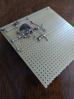
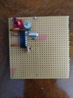
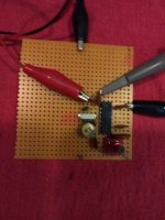
J310 JFET times two, emulating the dual gate 40673 MOSFET, in SMD format, the exception being the flying 1/8 watt 100K resistor to bias the gate of the upper JFET.
The load is a generic 10.7 MHz crystal filter. I am using a 60 MHz "FeelTech" FY6600 waveform generator as the LO. Looks like about 6-7 volts peak to peak is about the right LO drive level for this circuit.
Subjectively, the J310's seem hotter and quieter than the 2N3823's. The reduced footprint of the circuit is substantial, although the leaded / perf version could be made smaller than it is now.
It is going to take a bit of practice to get proficient with the SMD parts. There were certain parts of the circuit where 0603 might have been easier to work with than the 1206 parts.
Win W5JAG
Attachments
Another flash sale on eBay right now through this evening, for anyone interested .... $15 off a cumulative $75 purchase, applies to anything. I see about $75.01 worth of SMD components / stuff in my near future ....
Since I am starting SMD ab initio, I have decided the "sample book" small notebooks, and filler sheets to be a reasonable way to store the bulk of the parts, and is a convenient way to help build an inventory fast, so that is the road I am headed down - mostly 1206, some 0603.
Have both the first and second mixers built out in dual J310 SMD, HF => 45 MHz => 9 MHz => FT-817 using the FY 6600 as the LO's - it is not spectacular as an RF generator, but usable. It is easy to set a frequency, and useful to have a variable output voltage. The one I have is rated for a 60 MHz sine wave, and it will do that, but amplitude drops in the low VHF range. 5 volts is all it will do at 46 MHz. It wasn't expensive at all, and I got it for 20% off at that, so not complaining - it actually looks to be quite a bit of kit and has a surprisingly good manual. Takes up almost no space, comes with cables.
Some SMD inductors and more crystals showed up today, and it's been interesting playing with the crystal stuff, particularly the LM375, but I am seriously considering just getting one of those 54 MHz VCXO Crystek lumps for the 2nd LO and being done with it. Use what's been learned for a new crystal BFO. If the Crystek is good enough for mobile EME, it should work fine in the trunk of my car.
May build an unneeded vacuum tube something for a break before I plow back into this. I think this is the longest I've ever spent on an uninterrupted single project, with really nothing to show for it.
Win W5JAG
- Home
- Member Areas
- The Lounge
- No RF gear here?