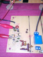
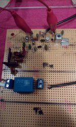
A simple 45 MHz IF amp - this is just my generic amp I've used in other projects, normally about 10 dB gain at the usual IF frequencies.
A couple of obvious flaws here - the red core toroid is a poor choice at these frequencies, but I had some red cores wound for other stuff, so I just used one of them here. The transistor is a 2N2222, probably another poor choice at this frequency.
Regardless, it seems to work well enough; I'm not looking for a lot of gain here - just enough to cover the loss in the filter(s).
When the first IF is sorted out, I'll probably follow this with another MOSFET mixer to the final IF, then move on to the ring mixers. I need to order some more SBL-1's or equiv. and some more 45 MHz filters.
Since it looks like the Si5351 can do +13 dBm into 50 ohms, would I be better off getting level 13 DBM's, or just use the level 7's with attenuators?
Win W5JAG
Attachments
Just a parenthetical -- but as the inventor of frequency skipping you might be interested in this film about Hedy Lamarr which is distributed by Zeitgeist Films and showing around the US at various locations. Bombshell: The Hedy Lamarr Story :: Zeitgeist Films
If Nikolai Tesla had her looks, he wouldn't have died broke!
If Nikolai Tesla had her looks, he wouldn't have died broke!
The MOSFET mixer at 45 MHz.
...
Do I still need to follow the output with a xtal filter, or will the single tuned circuit be sufficient selectivity to go to the next IF? I haven't thought much on the second IF - I have 10.7, 9, and 455 as options. I'd lost confidence in actually getting to this point.
...
Win W5JAG
Hi Win,
I had good result with Quadrature hybrid filter.
Quadrature Hybrid Bandpasss Filter
http://ftb.ko4bb.com/manuals/101.190.199.195/HF7070_receiver_article_Horrabin_QEX_2013.pdf
Cheers
Pascal
The KO4BB’s link is incorrect.
HF7070 receiver 1rst IF at 45 MHz
Another proven design from Australia
YouTube
Cheers
Last edited:
Thanks for those articles - I'll try to read them this weekend.
Very little time spent on the project this week. I changed the PN2222 out to a MPS3563 and it made a pretty big difference in the gain. Maybe too much; Ill probably add a gain control trimmer to set it where I want it.
At the lake this weekend, so unless I go back home early, won't be any work on it this weekend.
Win W5JAG
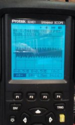
Second mixer - back to trainwreck status .....
I'm using 45.455 as a fixed LO to get to 455 KHz from 45 MHz.
In the example pictures shown, the DDS is set for 2 MHz, which gives a 47 MHz first LO. You can see the wicked mixing product at 1.545 MHz, which if my arithmetic is right, is the difference between 47 and 45.455. But I'm not sure that's what it is.
I first had it set up for 10.7 MHz second IF, and got an IF at that, but it was trashy - like it was self oscillating. I couldn't resolve that, so I moved it to 455 KHz where I could look at it with my simple scope, and found this frequency. The xtal filter should be blocking the first LO that is coming out of the first mixer - I know a single ended mixer passes everything straight through it including the LO - it's why I used the filter instead of an LC circuit.
I've tried bypassing the IF amp to rule out the possibility of it reamplifying the bit of LO that might get around / through the filter, and, at 10.7 MHz anyway, that had no effect - it was still trashy.
I'm going to play with it a bit tonight, and see if this is really a mixing product or a spur from the DDS.
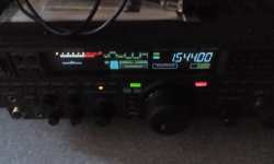
The scope shot is off the drain of the MOSFET, the FT-950 is capturing what is coming through the tuned circuit ....
Win W5JAG
I'm using 45.455 as a fixed LO to get to 455 KHz from 45 MHz.
In the example pictures shown, the DDS is set for 2 MHz, which gives a 47 MHz first LO. You can see the wicked mixing product at 1.545 MHz, which if my arithmetic is right, is the difference between 47 and 45.455. But I'm not sure that's what it is.
I first had it set up for 10.7 MHz second IF, and got an IF at that, but it was trashy - like it was self oscillating. I couldn't resolve that, so I moved it to 455 KHz where I could look at it with my simple scope, and found this frequency. The xtal filter should be blocking the first LO that is coming out of the first mixer - I know a single ended mixer passes everything straight through it including the LO - it's why I used the filter instead of an LC circuit.
I've tried bypassing the IF amp to rule out the possibility of it reamplifying the bit of LO that might get around / through the filter, and, at 10.7 MHz anyway, that had no effect - it was still trashy.
I'm going to play with it a bit tonight, and see if this is really a mixing product or a spur from the DDS.
The scope shot is off the drain of the MOSFET, the FT-950 is capturing what is coming through the tuned circuit ....
Win W5JAG
Attachments
OK. I checked three or four frequencies - they track, it's an image response.
I hooked a frequency counter up to the output of the 455 Khz IF xfmr, and of course it reads the fixed 45.455 LO blasting straight through the mixer and IF xfmr; I suspect this LO blowthrough was overloading the FT-950 receiver, and filling it with its own spurious responses.
I chased the 455 kHz xfmr with a ceramic filter of unknown specification, and it knocked the 45.455 LO down below the threshold that the frequency counter can detect, although the receiver still sees it as 60 over 9, or more - that's as high as it can read. The filter did greatly attenuate the image and killed all the other overload trash I was hearing.
The FT-950 is rated to receive to 30 kHz - they don't offer a sensitivity spec below 500 kHz, though. It's pretty darn deaf at 455 Khz at the antenna input, which makes sense, since its second IF is 450 kHz. This MOSFET board is a sharp tuner - the few signals strong enough to hear just snap in and out of the background.
I think with a decent crystal or mechanical filter at the second IF, this front end is probably OK to use.
The original plan, such that it was, was to use that 9 MHz SG-9 Mizuho board for an easy, no drama project, so I don't know if I'll just move on to that, or work on the DBM front end board next.
Win W5JAG
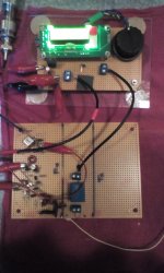
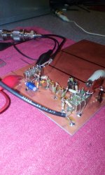
Another try at a DBM front end.
This incorporates ( I think ) all of the various suggestions - 45 MHz VHF first IF; DBM Mixer; broadband 50 ohm termination at the mixer; MMIC IF amplifier.
The MMIC is intriguing - this is the first time I've used one. It saved a lot of time and seems to work well. I didn't have a 78L05 to power it so I rigged up an LM317L. Preliminary results seem encouraging, but I haven't finished wiring the second mixer yet; I'm taking 45 Mhz off its input pin for now.
The xtal filter set is the $4 Tellurians.
I think the LO input level can be tweaked a bit to get the optimum level. The low pass filter can be cleaned up a bit. Maybe another MMIC at the input since this will be a mobile rig.
It looks fragile with the flying leads but it's quite rigid - should survive mobile use well. The caps are NP0 where it matters.
With two working front ends, some thought can now be given to the TX strip.
Win W5JAG
Attachments
Stupid DBM Question:
I don't have a DC blocking cap at the output of the MMIC. On the MMIC side of that 27 ohm resistor, I have 0.6 VDC. On the DBM input pin, I have 2.4 mVDC.
I put the 27 ohm resistor there as a precaution against oscillation in the MMIC. The MMIC is an NEC uPC1651.
Do I need a blocking cap here anyway? When the second LO is hooked up and switches the diodes on, will that look like a short to the MMIC, or will that 27 ohm resistor be enough to isolate the two?
The voltage at the power pin of the MMIC is 5.15 VDC, and if the TL-317L goes south, all of the positive voltage rail could eventually wind up at that pin, and that 27 ohm resistor won't limit the current much. Do I need one as a safety measure, if for no other reason?
Or is this worrying about nothing?
Win W5JAG
tentative preliminary observation, don't hold me to it:
Comparing the 45 MHz output of each board, the MOSFET board is quieter / more sensitive than the DBM board.
Attachments
I have no idea what the signal wave form would have looked like to blow up a TV set what ever it must have been a demon RF signal from hell.
I mean what are the odds of that happening? Sure TVI was common thing but blowing a TV set?
And people tell me that an EMP from a nuke can't damage modern electronics. hah.
Then again he could've just blamed you for the faulty tv set and wanted a freebie.
So, I found in my library, "Taking the Mystery Out of Diode Double Balanced Mixers", Joshi, Shankar*, QST, December, 1993, which is a good primer for dolts on these things.
That RF input pin is at DC ground potential, so, in many circumstances, a block is probably needed there. This MMIC does not use its output pin as a dc power input, which is why I omitted the block in the first instance. I really didn't even think about it until the next morning; then I looked at the schematic for the MMIC, and decided to check the voltages.
As it's applied with this MMIC, omitting it may still be an okay decision. I'm at the lake, so may be a bit before I can work on it again.
Win W5JAG
* Chief Engineer, Synergy Microwave
The same thing happened to me some weeks ago. I was driving a RF
transformer from a CMOS gate to produce a floating clock for my
analog switches in a chopper. I was thinking "That transformer looks
like a few 100 Ohms, that won't be much of a short." But it was.")
The CMOS output averages at 1.8Vdc.
transformer from a CMOS gate to produce a floating clock for my
analog switches in a chopper. I was thinking "That transformer looks
like a few 100 Ohms, that won't be much of a short." But it was.
The CMOS output averages at 1.8Vdc.
I am considering trying to build a tube based theremin, and am looking at forms for the inductors.
It occurred to me that it might be possible to impregnate cardboard with polystyrene by dissolving it in Toluene and soaking the tube in it the solution, then let it dry.
Thoughts?
It occurred to me that it might be possible to impregnate cardboard with polystyrene by dissolving it in Toluene and soaking the tube in it the solution, then let it dry.
Thoughts?
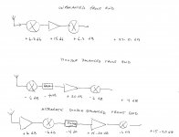
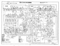
I think I have used up the usefulness of the FT-950 as an IF, so the next step is probably to pull the SG-9 board and get it into the chassis, or onto a breadboard, and test the front ends on it.
The SG-9 doesn't give an RX sensitivity spec. The examples shown in its manual depict it paired with a simple front end, consisting of an RF amplifier, and an active mixer, so I'm guesstimating it wants about 20-25 dB RF gain ahead of it.
The unbalanced MOSFET mixer board looks like it has about the right gain, with a good distribution. I'll change out the bipolar IF amplifier to a dual gate MOSFET to make it compatible with the AGC line on the SG-9.
The double balanced mixer board looks problematic. It lacks gain, and it looks to be badly distributed. It needs an RF amplifier.
Since everything is at 50 ohms, is it feasible to use one of these MMIC's as an RF amplifier between the low pass filter and the first mixer? Most of them seem to run around 3.5 to 5 dB on noise, which should be fine on HF. It would seem to be a vast improvement over - 10 dB or more.
Win W5JAG
Attachments
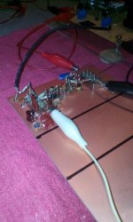
.... is it feasible to use one of these MMIC's as an RF amplifier between the low pass filter and the first mixer?
The answer looks to be .... maybe.
Can't tell much from the lousy cell phone picture, but I was trying to get a pic of another upc1651 stuck in between the low pass filter and the DBM module. These are nominally 19 dB gain at 500 MHz, and 5dB noise, regardless of frequency. I thought sure it would oscillate - the input and output are only about 5/16 inch apart, but it's not.
It's definitely an improvement, how much is hard to say, I've not played with it much. Both of the boards will eventually be tested against the other.
I'm not crazy about this synthesizer, so I ordered a new Si5351 synthesizer from QRP Labs. I've pulled the modules from the junktron, so I can start integrating, for lack of a better word, the new transverter(s) to the Mizuho SG-9 sideband generator.
I opened up the brick, and it looks like it uses MRF458 finals. They look pristine perfect, so, with a bit of luck, possibly the point of failure is one of the low level stages. I'm still quite a ways from worrying much about that.
Unfortunately, it is now warm and rainy ( floody ) here, which means mowing season starts again, probably as early as next week. This will make the heretofore glacial progress even slower.
Win W5JAG
Attachments
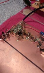
The MOSFET board, again. I was going to change the IF amp to a MOSFET, but just wired it as a second mixer, with the idea that I may be able to get enough conversion gain out of it to eliminate the need for an IF amp at 45 MHz.
And that may be feasible. The transformer on the output increases the gain. Unlike the first mixer, the second mixer does need LO attenuation. I don't know if this is due to output level variation between the variable and fixed output, variation due to frequency, transistor to transistor variation, or what. Getting the LO levels right has been frustrating, to put it mildly. I'm certain I'm not there yet, but I'm learning more about it, and getting closer.
The two crystals after the transformer are an attempt at a simple 9 MHz filter. I can't seem to find any monolithic 9 MHz filters, like are available for 45, 10.7, etc., so this is an attempt to fabricate one, from a batch of twenty crystals bought off eBay for a couple of bucks. This may have merit, probably does, but will be tedious trial and error to get it right.
Been listening to a French contest station on 20 most of the afternoon with this board.
Win W5JAG
Attachments
- Home
- Member Areas
- The Lounge
- No RF gear here?