Much earlier in this thread, there was discussion in some detail about switching and H mode mixers, but at the time they were just too far out on the learning curve for me.
The Trask mixer in that paper looks easy to implement and easy to try out.
The QRP Labs DC rcvr uses a similar switching mixer.
Win W5JAG
The Trask mixer in that paper looks easy to implement and easy to try out.
The QRP Labs DC rcvr uses a similar switching mixer.
Win W5JAG
The Trask mixer is one of the easiest and even has an antique equivalent with triodes. What makes it so pleasant to work with is the easy implementation. Remember that the 50 ohm requirement for diode mixers has a single reason: the transformers used are 50 ohm (industry standard) transmission line transformers which will produce "mayhem" when improperly terminated. Without those, you only need to take care that the mixer output sees a proper resistive load.
So the only issue with Trask and similar mixers is a symmetric LO signal, easier via a flipflop. With 2 of those plus RF or AF 90 degree phase shifter you can make a real SSB RX: with a simple DC RX you can't properly tune to a DSSC signal.
So the only issue with Trask and similar mixers is a symmetric LO signal, easier via a flipflop. With 2 of those plus RF or AF 90 degree phase shifter you can make a real SSB RX: with a simple DC RX you can't properly tune to a DSSC signal.
Aridace,
Do you think there were no overload problems back in the R390 days (Navy Daze).
Try finding an antenna on a USN Fletcher Class Destroyer that did not have very large signals.
The ship is transmitting on multiple antennas all over the ship, not just listening.
I remember the input coil and capacitor of the Old Loran receiver that was totally burned out, when a radioman made the mistake of connecting a 500W transmitter to an antenna that was next to the Loran antenna.
Do you know what happens to the silicon mixer crystal of a 10GHz surface search radar . . .
When the antennas of two destroyers points at each other briefly as they are both coming around?
No radar's TR and ATR tubes can protect against that!
Pulse radar? No, BANG Radar!
Back in the days of the Soviet woodpecker I was working with a student on a design of a semiconductor 10 Khz-30 MHz communications RX and when the woodpecker no longer was active every day, I decided to make a replacement, to continue developing the noise blanker for it. After powering up that replacement, all computers in the building crashed and the one developing computers reported that whatever in his lab he had in memories was completely erased. Fortunately the student was able to suppress laughter till back in my lab.
They'll definitely overload your back if you have to carry one across a hamfest and then out to the trunk of your car ....
For those unfamiliar with the woodpecker:
https://en.wikipedia.org/wiki/Duga_radar
I still remember jamming it with CW.
Win W5JAG
For those unfamiliar with the woodpecker:
https://en.wikipedia.org/wiki/Duga_radar
I still remember jamming it with CW.
Win W5JAG
When such interference occurs, in Panama you first have to file a complaint (power company) and when not addressed within 2 weeks, next step is to file a complaint with proof of having filed a complaint at the power company plus all technical data involved to the govt. dept. of telecommunications, as according to the law, every inhabitant of Panama has the right to receive every MW station (and there are many, mostly ~ 1KW).
It's simpler than that: apply a slew rate filter. In the sim pic, V4,5 is the 100 µV input signal, V4 has the noise pulses of 100 mV added, V9 is an internal signal of the filter, V2 the output of the filter, and V12 the (10 KHz) filtered output. While not perfect, for CW it would perform much better than on the sim.

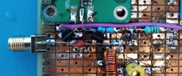
As can be inferred from the very small space between the bandpass filter and the mixer board, I did not anticipate installing an RF amp, but the NF on that AD831 is high, and after the fact I thought that if I wanted to use it above 7 MHz or so, I would need one. The MAR-6+ (barely) fits, and where it is placed, it will work with any filters still to be installed, plus the aux input.RF amp before the mixer makes it more prone to overload from local stations, so in a rural region the RF stage might be OK.
Today, I added in a pair of the same may or may not be PIN diodes in an attenuator similar to that used in the broadcast receiver, so if overload becomes an issue, that should handle it. The board is in really poor shape in this area, but there was enough room left to squeeze them in. The AD831 board covers the worst part of it and is why it is placed in that spot. If I had thought more about project creep before I started, I might have done it different.
In addition to the attenuator, I added a 3 KHz low pass filter to narrow the audio channel, and generally cleaned things up around the audio strip, cut way back on the flying leads / sky wires, etc.
It works pretty well. It still needs something to level the audio peaks. It doesn't sound like it needs a whole lot - 20 dB gain variation might do it.
Win W5JAG
Attachments
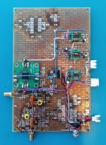
Not much space indeed. But in a rural region especially above ~15 MHz, a 10 dB NF often is too high. A slew rate filter is the proper means to prevent ear damage and it sounds much better than a clipping amp with LF filter. The main difference is that when a slew rate filter is overdriven, the output waveform resembles a triangular one. Apart from that, high peaks (electric storms etc.) with short risetime are as if "swallowed", they don't appear at the output. So in theory it's possible to make a MW DC RX, with 1 PLL, extra product detector, a phase shifter and such a slew rate filter. Remember the NE561?
- Home
- Member Areas
- The Lounge
- No RF gear here?