SKY and MACOM also make pin diodes. (and the NXP family).
Avago/Broadcom has axed most of the HP simple components.
They did not kill the HLMP-6000, a dim red LED that I like for
its low noise when abused as a reference.
BTW you cannot simulate PIN diodes in Spice, it does not know
about carrier lifetime. Some manufacturers have created models
that are just a resistor that depends on DC current.
With a high IF, you might use PINs there and at least protect the 2nd mixer.
cheers, Gerhard
Last edited:
The details of building a Multipoint Distribution System receiver for the two NTSC video channels at 2.15, and 2.156 GHz with plans for a simple receiver were in one of the ham radio magazines back in 1978 or 1979. I can't find it now with a simple internet search, but it wouldn't matter today, those frequencies are used for cell phones now.
I have CD-ROM of "QST", and "Ham Radio" from that era.
My first guess was 73 or QST since our ham club had subscriptions for both back then.
I did some searching online, and found one article describing MDS, but nothing on building a device with a pair of the HP diodes, some copper flashing suspended in the air above PC board material and a couple transistors (or dual gate mosfets) for an IF amp. The LO might have used a piece of semi rigid coax for the resonator, or that could have been something that I developed later, don't really remember.
My old brain probably can't come up with the right search terms, since phrases like "pirate HBO" would not be used in a proper ham radio magazine.
I wound up designing my own version a couple years later just to one up an arrogant high level engineer who bragged about being able to pick up the signal from Miami when he lived 20 miles away. I lived 35 miles away and got a better picture than he did. I used PLL to eliminate drift, and a GaAs fet LNA for a 1db or less noise figure.
It doesn't much matter any more, but the same techniques could be used in the 2304 MHz ham band.
I changed the 10.7 MHz slug tuned transformer to a 7 mm 455 KHz transformer.
Device gain increased quite a bit; more than I expected. It is now good for about 33 dB gain, or 0 dBm on the RP. It attenuates all the way to the noise floor of the RP, so at least 75 - 80 dB gain variation.
This transformer is as broad as the proverbial barn door. I did not expect that.
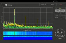
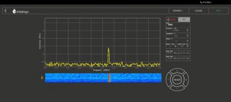
Picture 3 was made using the peak hold function of the RP to illustrate the bandwidth of the circuit. The - 6dB points are about 50 KHz either side of the center frequency. You can see the second harmonics of everything off to the right side of the graph. The second harmonic is only down 40 dB.
These transformers could probably be used for FM at 455 KHz. It is the yellow core, which I believe is the highest impedance of the 455 KHz variants, so the best match for the MOSFET. I have some 10 mm variants, but they don't fit as well on these breadboards. I don't know if they tune any sharper.
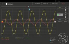
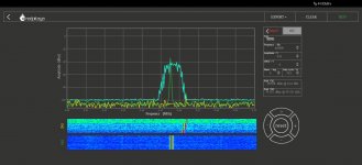
Picture 1 shows the 455 KHz input from the RP looped back into channel 2 ( green ) and frozen for the baseline reference. Yellow is the output of the MOSFET at max gain. Picture 2 is the RP scope function. Red is input. Yellow is output, again at max gain.
Not sure if I will work on this anymore today - I'll probably watch basketball. One of the tank cases against me ( case #2 ) went to trial last week, it went well but the judge adjourned it so some more evidence could be gathered. It does not reconvene until late June. Case #1 is set for next week or the week after, but it really turns on the outcome of #2 so will be postponed until late summer. This drama has been going on since late 2002. Not a typo.
Device gain increased quite a bit; more than I expected. It is now good for about 33 dB gain, or 0 dBm on the RP. It attenuates all the way to the noise floor of the RP, so at least 75 - 80 dB gain variation.
This transformer is as broad as the proverbial barn door. I did not expect that.
Picture 3 was made using the peak hold function of the RP to illustrate the bandwidth of the circuit. The - 6dB points are about 50 KHz either side of the center frequency. You can see the second harmonics of everything off to the right side of the graph. The second harmonic is only down 40 dB.
These transformers could probably be used for FM at 455 KHz. It is the yellow core, which I believe is the highest impedance of the 455 KHz variants, so the best match for the MOSFET. I have some 10 mm variants, but they don't fit as well on these breadboards. I don't know if they tune any sharper.
Picture 1 shows the 455 KHz input from the RP looped back into channel 2 ( green ) and frozen for the baseline reference. Yellow is the output of the MOSFET at max gain. Picture 2 is the RP scope function. Red is input. Yellow is output, again at max gain.
Not sure if I will work on this anymore today - I'll probably watch basketball. One of the tank cases against me ( case #2 ) went to trial last week, it went well but the judge adjourned it so some more evidence could be gathered. It does not reconvene until late June. Case #1 is set for next week or the week after, but it really turns on the outcome of #2 so will be postponed until late summer. This drama has been going on since late 2002. Not a typo.
Attachments
At low IF like 455KHz it's fairly easy to get textbook ( = close to ideal) performance - without any of the compromises of "el cheapo" commercial solutions. Amplifiers can have high and stable gain, demodulators can have low distortion. One can even "abuse" a simple audio amp to work as AM demodulator - THD in the 0.0X region (issue has been posted several years ago).
... Most PIN diodes can be used as attenuators but some, especially those designed to be used as switches may have a very narrow range of attenuation. The only way to find out is to try them. ...
So, I tried them.
And pulled that broad as a barn door "tuned" amp off the board to make room for a ceramic filter. About the best AM filter I could find in stock was a Murata CFU455H3. Specs attached. The bandwidth looks about right - I made a crude sweep of the pass band by using the max hold function on the RP, and just bumping the oscillator frequency one KHz at a time up and down to sort of show the passband. There looks to be ripple across the passband, more than the spec allows, but my matching is probably mediocre. I have an LC network on the input, and a 2K resistor on the output. On the good side, I expected a lot of blowby, but the skirts look okay for a ceramic filter.
Attenuator - how much attenuation should I expect? I am getting 30 dB attenuation according to the RP.
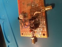
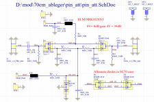
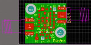
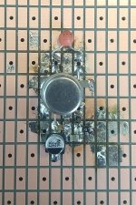
I am using the same 0 to 4 vdc source as used for the DG MOSFET bias. The diodes are the unmarked devices that I think are PIN diodes, but am not really sure. The circuit is as simple as I could make it - a current limiting resistor to the two diodes in series, with blocking capacitors to get the RF through the junction of the two diodes.
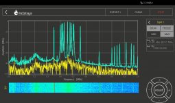
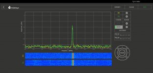
In all the pics, channel 2 (green ) shows the input level from the RP and frozen for the point of reference. First pic shows the loss through the filter / attenuator at minimum attenuation. The RP shows the overall loss at 7 dB, and the filter is specified as 6 dB insertion loss, so this looks okay to me.
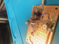
Second pic is the passband. Third pic is the maximum attenuation. The other two are bad pics of the device - once the pads are tinned, it's like trying to photograph against a mirror.
Attachments
Haven't really forgotten about this - just haven't had much time to fool with it.
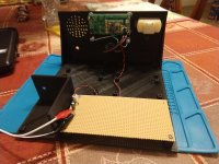
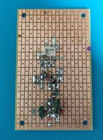
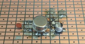
The variable local oscillator is built, and mounted and wired in to the breadboard. I was going to start mounting and testing some of the built up boards, but wound up wasting an hour and a handful of transistors and zener diodes making voltage regulators the old way, for no particular reason other than curiosity.
The giant piece of perf is for all of the non RF stuff.
Then I had to get some mowing in before it started to rain again.
Attachments
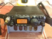
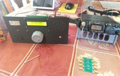
I found a tilt stand for the FT-817 on thingiverse, so I printed it out. It makes the FT-817 somewhat easier to use. Looking at the '817 specs, 45 MHz is not listed in any of its receiving frequency bands, but it does tune to 45 MHz and seems to work okay there.
With the FT-817 as a back end, I put the low pass pass filter / first mixer on the breadboard to make sure they worked in the real world. It seemed to work okay so I took it back off to ( try to ) match the TUF-3 ports.
I left the RF port alone since it should have 50 ohms on the antenna.
The Si5351 is supposed to be 50 ohm output, but I added a 2 dB 50 ohm pad to the LO port anyway - I measured my parts and put them into the calculator and it came out 1.95 dB with -75 dB return loss. This could be problematic as the RP only shows the Si5351 to have about 0 dBm output at 45 Mhz, although it has about 8.5 dBm at lower frequencies like 10 Mhz. I don't know if this is a measurement error, or if the Si5351 output actually falls off at higher frequencies. It could be worse at 75 MHz - I don't have anything that can see that high right now. So I may need to come back later and add a buffer amplifier to the LO.
I put a 45 MHz 50 ohm diplexer on the IF port - I haven't had much luck with SMD inductors, so I just wound the coils on T25-10 ( black ) cores.
There is still room for an RF amplifier if I need one. The TUF-3 data sheet shows that conversion loss goes up as LO drive goes down, but even with the low LO drive, it still seems more than quiet enough on 20 meters, which is the highest I have tried to listen to anything.
Attachments
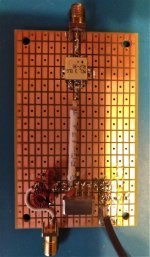
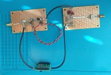
I added in the bits to match the 45 MHz filter in and out of 50 ohms. As before, since I have had unsatisfactory results with SMD, and all my small value solenoid wound inductors are back home, I just wound the coils on T25-10 (black) cores. I left room to put the PIN diode attenuator between the filter output and amplifier input, but for simplicity, it is not installed at present.
Since I am still uncertain about the second IF frequency, the mixer output just goes straight to the output connector. I soldered everything together without any connectors on the RF connections, which saved some time, and is not too big an inconvenience at present. This may or may not change later. Purely as a matter of immediate convenience and simplicity, I am using the fixed second output channel of the Si5351 as the fixed second LO for preliminary testing purposes.
This front end seems to be completely satisfactory in operation. With the FT817 as a back end, and its RF amplifier switched off and RF attenuator turned on, connecting a random piece of wire about a dozen feet in length to the 50 ohm input of the first mixer board causes an increase in the background noise level up to at least 15 MHz ( highest I have tried so far). Signals just pop out of a quiet background. It may need an RF amplifier at higher frequencies, but for now I am satisfied with the sensitivity.
I tried it on the MW broadcast band against a modern "transistor" radio - probably just a loopstick going into an SI4735 or similar, and one of the old higher performance "super" portables that have an RF amplifier, and even with just the short unmatched piece of wire for an antenna, it is obviously superior to both; it is in no way subtle. The super portable is very sensitive, but it's noisy. The homebrew setup is sensitive and quiet. Signals that are rough copy on the super portable because of noise, just pop right out of the quiet on the homebrew front end, and are Q5 copy.
I didn't get very good results from diode mixers before, so I was not really expecting much here, and I am quite surprised that this preliminarily appears to work well beyond my expectations. The Si5351 channel cross talk that was completely unsatisfactory with the single ended MOSFET mixers does not seem to be an adverse factor here, at least in the limited testing so far.
Presently I am using 54 MHz high side second LO injection to a 9 MHz second IF. Since I am not certain of the final IF frequency, there is no diplexer on the second mixer output. I had intended to ultimately have a crystal controlled second LO, but that may not be necessary. Probably too soon to really say one way or the other.
Question: how important is impedance matching the mixer LO input? On the second mixer here at present, the second channel of the Si5351 goes directly to the mixer LO input, and this seems satisfactory. If LO port matching is not that important, I'll remove the attenuator on the first mixer LO input and pick up that extra 2 dB of drive.
Attachments
Thanks Gerhard.
When I decide on a second IF frequency, will I also need a diplexer on the output port of the second mixer as is required on the first mixer?
That could influence my choice of second IF.
The output impedance of the mmbt5179 first IF amplifier should be 50 ohms, but I have no real way of measuring it, so I think I'll pull that 50 ohm 2 dB LO attenuator from the first mixer, and put it in between the output from that bifilar xfmr and the input port of the second mixer. Completely by accident, I laid out the board to easily accommodate that, and that circuit has plenty of gain.
Since it looks like AGC can be handled with the PIN diodes, I'm considering recycling that circuit for another try at a broadband IF strip.
I may get some free time this weekend to work on it a bit more.
As usual, it depends. Probably, the levels at the 2nd mixer are
larger which would make it more important, but then it is after
the first crystal filter which decreases the number of combatants
at the 2nd IF. There is no clear win/win.
I have cut some groups of my 432 MHz transverter to stamp-size
boards and will send them early next week to JLCpcb.
larger which would make it more important, but then it is after
the first crystal filter which decreases the number of combatants
at the 2nd IF. There is no clear win/win.
I have cut some groups of my 432 MHz transverter to stamp-size
boards and will send them early next week to JLCpcb.
Attachments
Last edited:
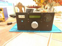
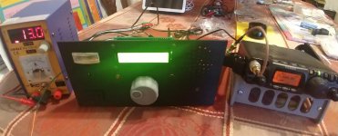
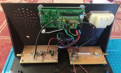
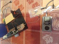
A temporary IF strip / detector built around a National Semiconductor LM372, while I figure out how I want to proceed with this receiver.
The board shows a bit of rework as, after thinking about it a bit, I reworked the RF side to be able to get in and out of the AGC / Gain block ( shown connected together with the 10 nF disc ) without crossing over the RF input to avoid stability issues. It is completely stable as shown, but will oscillate if the RF input is disconnected.
I am using it at 455 KHz and sensitivity is adequate for local stations and strong shortwave stations. I'm listening to WTWW ( the big 5085 ) on it right now. AGC is surprisingly good - better than the FT817 in AM mode. The detector is audibly considerably lower in distortion than the AM detector in the FT817. It is probably possible to build a very usable and simple AM only receiver around this chip.
The LM372 chip used here has a date code of 6933. There is an August, 1968, application note, AN15, that describes the operation of the chip in exquisite detail, but it seems to be too big to attach. There is also a November 1972, 73 magazine article written by its designer, Bob Hirschfeld, W6DNS, which likewise seems too big to attach, and who is arguably even more interesting than the chip. An MIT grad, in addition to designing the LM372, he also designed the LM370, the LM373/374, the LM3909 LED flasher, probably the LM371 and LM375, then he left National, went to law school, started the fathers rights movement that was just getting going when I was in school, and ultimately wound up disbarred.
The little device the LM372 is feeding is a Degen DE28. These things do AM FM SW MP3 and have an aux input to use it as a powered speaker, as shown here. $20 USD including shipping on Ebay.
Attachments
Last edited:
455 Khz IF - why did this become the de facto standard?
I built a simple matching network to go from the 50 ohm impedance of the second mixer to the 3K input impedance of the LM372, which made a noticeable improvement to sensitivity.
I also played with the IF a bit, and found that both 450 KHz and 460 KHz were noticeably better than 455 KHz in terms of beat and other high frequency trash. Right now the only filtering is at 45 MHz, so I don't know if this is an artifact of no filtering at the second IF, channel crosstalk in the Si5351 output, or something else. I played around with a calculator, and didn't see an obvious reason for this.
I also notice that filters are readily available for both 450 and 460 Khz, in addition to 455 KHz, so I can't be the first person to observe this. This weekend I'll add some filtering at 455 KHz to see if that changes anything. I ordered some surplus AM bandwidth 450 KHz filters from ebay to hedge my bets, but I doubt they'll show up before the weekend.
edit: second LO injection is at 44.545 MHz, because crystals are still available for that frequency.
Last edited:
Short story of IF frequency here SolderSmoke Daily News: Radio History Question: Why 455 kHz as the IF frequency?
With only 1 LC selection for a single ended mixer, there was the problem of IF breakthrough (maritime communication) plus IF oscillation so the better sets employed a tuned RF preamp. DIY-ers like me employed a 7360 balanced mixer to avoid such issues plus the overload issue as the 7360 mixer had a low noise figure.
With only 1 LC selection for a single ended mixer, there was the problem of IF breakthrough (maritime communication) plus IF oscillation so the better sets employed a tuned RF preamp. DIY-ers like me employed a 7360 balanced mixer to avoid such issues plus the overload issue as the 7360 mixer had a low noise figure.
- Home
- Member Areas
- The Lounge
- No RF gear here?